background image

CDi-16B - Installation and operating manual 

www.omega-air.si 


Operating 


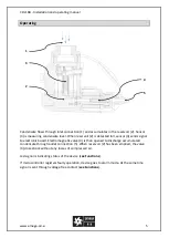
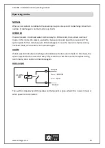
Condensate flows through inlet connection (1) and accumulates in the reservoir (2). Sensor 
(3) is measuring condensate level. When reservoir (2) is detected full, sensor (3) sends signal 
to electronic board. Electromagnetic valve (4) is than opened to discharge accumulated 
condensate through outlet connection (5). When reservoir (2) has been emptied, the valve 
(4) closes back without any losses of compressed air. 

Led signal is indicating status of the device (

see Functions

). 

If microcontroller registers faulty operation, device goes to alarm mode. At the same time 
signal is sent through voltage free contact (

see Functions

). 


Summary of Contents for CDi-16B

Page 1: ...tion and operating manual CDi 16B Please read the following instructions carefully before installing electronic drain unit into service Trouble free and safe operating of the unit can only be guarante...

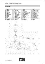
Page 2: ...ng 21 95x1 78 4 Damper 14 Screw plug 1 2 24 Screw PT KA 35x16 34 Screw KA 30x8 5 Valve housing 15 Connection Al 50 25 Foil keyboard 35 Screw KA 30x8 6 Plunger 16 Fixing screw 1 8 26 O ring 38 0x3 0 36...

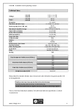
Page 3: ...5 C 35 to 149 F Upper Inlet connection G 1 2 BSP Lower Inlet connection G 1 2 BSP Outlet connection G 1 8 BSP Power interface 3 x 0 5mm 2 Protection class IP65 Volume 0 1 l Mass 0 96 kg Dimensions A x...

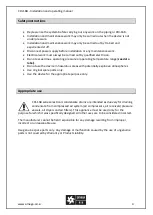
Page 4: ...abel Do not use the device in hazardous areas with potentially explosive atmospheres Use original spare parts only Use the device for the appropriate purpose only Appropriate use CDi 16B series electr...

Page 5: ...gnal to electronic board Electromagnetic valve 4 is than opened to discharge accumulated condensate through outlet connection 5 When reservoir 2 has been emptied the valve 4 closes back without any lo...

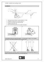
Page 6: ...commended Install ball valves 2 only Recommended connection 4 to water oil separator 1 2 The inclination of the unit must not exceed 5 in both axes If device is not installed correctly it could cause...

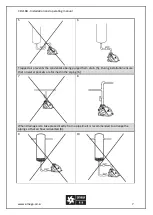
Page 7: ...ped air prevents the condensate being purged from drain 5 During installation ensure that no water pockets are formed in the piping 6 7 8 When drainage is to take place directly from a pipeline it is...

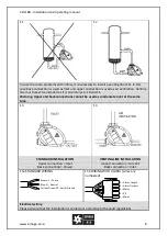
Page 8: ...11 Warning Upper and back connections cannot be used as condensate inlet at the same time 13 14 STANDARD INSTALLATION Upper connection Inlet Back connection Closed VENTING LINE INSTALLATION Upper con...

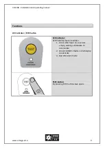
Page 9: ...ctions LED indicator TEST button LED indicator LED indicates device condition 1 Green ON Power on reservoir empty waiting condensate to accumulate 2 Green FLASHES Device is discharging condensate 3 Re...

Page 10: ...osed for one second This cycle repeats for five minutes up to 100 discharges In case the reservoir empties during overload mode device enters normal mode again ALARM If drain was still not able to dis...

Page 11: ...nce work take the drain out of operation switch off the power supply and depressurize the unit Service kits Based on type of CDi 16B drain following servis kits can be used SERVIS KIT CDI 16 B 230V SE...

Page 12: ...lisation passed by After connection wait 2 sec for system initialisation Check for voltage in circuit Check the cable and power connection Connect CDi 16B to proper voltage Mistake must be repaired by...

Reviews: