omal automation AGO DA2880 Instruction Manual Download Page 6

Rif. UMA800081C - 06/22

IT

EN

EN - 

6

OMAL S.p.A.

Headquarters

: Via Ponte Nuovo, 11 - 25050 Rodengo Saiano (BS) Italy  •  

Production Site:

 Via Brognolo, 12 - 25050 Passirano (BS) Italy

Ph.

 +39 030 8900145  •  

Fax

 +39 030 8900423  •  [email protected]  •  

www.omal.com

INSTRUCTION MANUAL

AGO: SCOTCH–YOKE PART TURN PNEUMATIC ACTUATOR

DA2880 - DA8000 - SR1440 - SR4000

g. Lubrification.

The actuators are lubricated, for normal working conditions, in the company. For maintenance or reassembly operations, OMAL S.p.A. 

recommends the use of a lubricant such as TECNOLUBE SYNTHY POLYMER 402 or equivalent. 

h. Functional Safety

The OMAL S.p.A. pneumatic actuators are also suitable for installations which require high level of functional reliability, up to SIL3, in 

compliance with the IEC 61508 standard.

i. Wear protection of internal components 

The cylinder is electrolysis nickel plated internally, in order to reduce roughness of the surface

to a minimum value and is protected with an oxidation treatment which is 20μm thick. The guides of the pistons are made of acetalic 

resin. The use of steel bushes on the Scotch yoke system reduce backlash and confer very low friction sliding during operation.

j. External protection

The actuators are suitable both for indoors and outdoors. The aluminum body and the caps are protected against corrosion by an 

oxidation treatment which is 20 µm thick; the shaft and cap screws are made of stainless steel.

This generally allows to meet the C4 safety class, for applications that require it, according to the standard EN 15714-3 section 4.4.3.

For applications in environments with aggressive type atmospheres that require a higher protection level than C4, the actuator must 

be protected with a suitable varnishing treatment. 

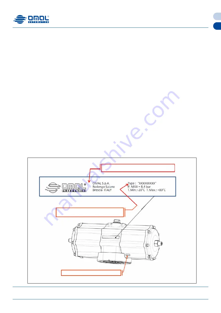
k. Marking and classification

The bodies of the OMAL S.p.A. actuators are marked, by means of laser engraving or a label, with the manufacturer’s logo and ad-

dress, the code or the serial number, the size, the output torque, the working pressure and the maximum working temperature and 

the production date.

Marking of versions where the temperature is different from the standard one:

low temperature version: T. min.= -50°C  T. max=60°C

high temperature version: T. min.= -20°C  T. max=150°C

1) Logo and address of the manufacturer

2) Product code including the series “DA” the no-

minal torque “XXXX” and their type of flange “FXX”

3) Production date code “XX/XX”

Summary of Contents for AGO DA2880

Page 1: ...Rodengo Saiano BS Italy Production Site Via Brognolo 12 25050 Passirano BS Italy Ph 39 030 8900145 Fax 39 030 8900423 info omal it www omal com DA DOUBLE ACTING VERSION SR SPRING RETURN VERSION INSTRU...

Page 2: ...tuators for industrial valves IEC 61508 2010 1 7 Functional safety of electrical electronic programmable electronic safety related systems Part 1 7 UNI CEN TS 764 6 2005 Pressure equipment Part 6 Oper...

Page 3: ...point equal to 20 C or to be at least 10 C below the ambient temperature ISO 8573 1 Class 3 The maximum particle size shall not exceed 40 m ISO 8573 1 Class 5 c Operation pressure The maximum operatin...

Page 4: ...25050 Passirano BS Italy Ph 39 030 8900145 Fax 39 030 8900423 info omal it www omal com INSTRUCTION MANUAL AGO SCOTCH YOKE PART TURN PNEUMATIC ACTUATOR DA2880 DA8000 SR1440 SR4000 Note different worki...

Page 5: ...olo 12 25050 Passirano BS Italy Ph 39 030 8900145 Fax 39 030 8900423 info omal it www omal com INSTRUCTION MANUAL AGO SCOTCH YOKE PART TURN PNEUMATIC ACTUATOR DA2880 DA8000 SR1440 SR4000 Note differen...

Page 6: ...stem reduce backlash and confer very low friction sliding during operation j External protection The actuators are suitable both for indoors and outdoors The aluminum body and the caps are protected a...

Page 7: ...on with the side chambers of the cylinder by pressurizing such connection of a standard double acting actuator DA the shaft rotates counter clockwise to open while port 4 is connected with the interme...

Page 8: ...aps when the actuator is installed online or while it s still pressurized Do not remove the spring cap this operation may be carried out by qualified personnel only such operation could cause personal...

Page 9: ...y to see whether if it s suitable for the application or not Remove the plastic protective covers from the ports and insert whichever filters as pointed out in paragraph 2 Prior to mounting the actuat...

Page 10: ...here direct installation is not possible the right solution is given by a bracket and a connecting joint The bracket is a steel bridge that allows to connect the valve on one side and the appropriate...

Page 11: ...justment of the actuator is possible in both open and closed positions By operating on the adjusting center block A the opening can be adjusted while the closing can be adjusted by turning the two scr...

Page 12: ...aft External chambers supply hole 1 Make sure that both chambers are pressurized 2 Unscrew the protection cap completely 3 Rotate the screw 2 in a clockwise direction if you want to increase the openi...

Page 13: ...unter clockwise direction if you want to increase such angle both screws must be rotated of the same amount 4 Tighten the nuts 3 4 5 Pressurize the internal chamber with the least pressure enough for...

Page 14: ...A8000 SR1440 SR4000 ACTUATOR DA 2880 The adjustment of the actuator is possible in both open and closed positions It can be adjusted by turning the side screws A B ATTENTION Any type of adjustment mus...

Page 15: ...C ACTUATOR DA2880 DA8000 SR1440 SR4000 1 Make sure that both chambers are not pressurized 2 Loosen the lock nut 1 3 Rotate the screw 2 clockwise to decrease the opening angle in a counter clockwise di...

Page 16: ...ACTUATOR DA2880 DA8000 SR1440 SR4000 Shaft Central chamber supply hole External chamber supply hole 1 Make sure that both chambers are not pressurized 2 Loosen the lock nut 3 3 Rotate the screw 4 cloc...

Page 17: ...nd closed positions By operating on the adjusting center block A the closing can be adjusted while the opening can be adjusted by turning the two screws B ATTENTION The adjustment and checking must al...

Page 18: ...d of the same amount 4 Tighten the lock nuts 3 4 5 Pressurize the internal chamber with the least pressure enough for the movement of the internal pistons it can be seen precisely from the shaft rotat...

Page 19: ...VALVE ADJUSTMENT 1 Pressurize the internal chamber central with the least pressure enough for the movement of the internal pistons it can be noticed from the outside due to the partial rotation of th...

Page 20: ...both open and closed positions By turning the side grub screw A the closing can be adjusted while the opening can be adjusted by turning the side screw ATTENTION The adjustment and checking must alwa...

Page 21: ...3 3 Rotate the screw 4 in a clockwise direction to decrease the opening angle and in a counter clockwise direction to increase such angle 4 Tighten the lock nut 3 5 Pressurize the internal chamber wi...

Page 22: ...central supply hole Shaft CLOSED VALVE ADJUSTMENT 1 Pressurize the internal chamber with the least pressure enough for the movement of the internal piston it can be noticed from the outside due to the...

Page 23: ...que a Nm Least number of cycles expected for pistons and cylinder b Least cycle rate from 0 90 in seconds s 125 500 000 c 3 1 000 500 000 5 2 000 250 000 8 8 000 100 000 15 32 000 25 000 20 63 000 10...

Page 24: ...RIALS Pos Description Pos Description 1 Description 22 Yoke Scotch yoke 2 Steel bush 23 Shaft bearing support 3 Steel pin 24 O ring 4 Body 25 Upper support 5 Nut 26 O ring 6 O ring 27 External support...

Page 25: ...s Description Pos Description 1 Cylinder 20 Lower shaft O ring 2 Piston 21 Cap O ring 3 Cap 22 O ring Body cylinder 4 Shaft 23 Cap nut 5 Yoke 24 Adjustment screw 6 Shaft bearing 25 Screw O ring 7 Shaf...

Page 26: ...Steel bush 17 Interface F25 33 Piston 2 Steel pin 18 Interface screw 34 Yoke 3 Adjustment screw 19 O ring 35 Shaft bearing support 4 Left stop 20 Shaft bearing 36 O ring 5 O ring 21 Disks 37 O ring 6...

Page 27: ...2 Steel pin 19 O ring 36 O ring 3 Adjustment screw 20 Shaft bearing 37 O ring 4 Left stop 21 Disks 38 Body 5 O ring 22 Spring pin 39 Upper support 6 Protection cap 23 Side Cylinder 40 O ring 7 Anti r...

Page 28: ...l bush 17 Cap nut 33 O ring 2 Steel pin 18 Grub screw cap 34 Bearing piston head 3 Body 19 Nut 35 Side Cylinder 4 Internal spring 20 Adjustment screw 36 O ring 5 O ring 21 O ring 37 Cap 6 Shaft 22 Yok...

Page 29: ...Adjustment screw 21 Bearing Disks 39 Upper support 4 Left stop 22 Spring pin 40 O ring 5 O ring 23 Side Cylinder 41 External support ring 6 Protection cap 24 O ring Cap O ring 42 Washer 7 Anti rotatio...

Page 30: ...nder 43 Seeger 4 Left stop screw 24 O ring Cap 44 Carter seal 5 O ring 25 Cap 45 Washer 6 Protection cap 26 Assembly screw 46 Seeger 7 Anti rotation washer 27 Cap nut 47 Cylinder reduction flange 8 Me...

Page 31: ...re made of stainless steel AISI316 c Normally open spring return version The normally open spring return version is required in the cases where if there should be a pressure or power failure the valve...

Page 32: ...air supply Mechanical stop if there not duly adjusted Adjust the stops by increasing the stroke Wrong connection between the actuator hole and the valve stem Check the connection and the size of the a...

Page 33: ...SR4000 12 DECLARATION OF CONFORMITY The OMAL S p A actuators have been designed manufactured and tested to meet the requirements of the following European stan dards and are marked where provided wit...

Page 34: ...plied to the products for UK market OMAL S p A declares that the products are in CONFORMITY with the essential safety requirements of the of the above mentioned Regulations providing that declared per...

Reviews: