background image


21 

– CLEANING AND MAINTENANCE 

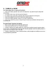
Cleaning and maintenance after every use;


  Make sure that the plug is not plugged in, or the switch is turned off while cleaning the 

device. 

  Clean the surface of the device after each use.  

  After each use, clean the dough residues accumulated on the surface of the tray.  

  Do not use abrasive cleaning chemicals as these can leave harmful residues. 

  Do not use pressurized water and steam while cleaning the device. 

  Do not clean the outer stainless surface of the device with cleaner that can scratch the 

material such as wire wool. 
 

Periodic cleaning and maintenance;


  Maintenance should be done by qualified person. 

  Get the periodic maintenance of the appliance once in every 15 days. 

  Check whether the waffle trays have lost their non-stick feature according to the frequency 

of use. Otherwise, chemicals harmful to health originating from Teflon material will do harm 
food and therefore human health. 

  According to the frequency of use, the electrical maintenance of the device should be done 

by spraying dry air after the electrical connection is cutcut. 


Summary of Contents for Omk.WFL51.E12.0601.Z5F

Page 1: ...HAN OSB MAH ATABEY SOK NO 5 SEL UKLU KONYA T RK YE FABR KA HOROZLUHAN OSB MAH BAYRAMPA A CAD NO 7 1 SEL UKLU KONYA T RK YE TEL 90 332 222 00 00 FAX 90 332 222 01 01 www omake com tr info omake com tr...

Page 2: ......

Page 3: ...3 A3 TA IMA ve SAKLAMA ARTLARI Sayfa 3 A4 PAKET A MA Sayfa 3 B KURULUM Sayfa 4 C GENEL UYARILAR Sayfa 5 D KULLANIM B LG LER Sayfa 6 E TEM ZL K ve BAKIM B LG LER Sayfa 7 F SORUN G DERME Sayfa 8 G DEMON...

Page 4: ...AVUZU LERDE GEREKL OLDU UNDA KULLANMAK ZERE G VENL VE KOLAY ULA ILAB L R B R YERDE SAKLAYINIZ RET C BU K TAP I IN EV R YA DA BASIMINDAN KAYNAKLANAN C HAZIN HATALI KULLANIMINDAN DO ACAK NSANA EVRES NE...

Page 5: ...uzak olmas durumunda yava hareket edilmeli gerekirse sallant lara kar cihaz sabitlenmeli veya bir ki i taraf ndan dengesi korunmal d r r n ta rken bir yere arpmay n z ve d rmeyiniz r n ilk al t rmada...

Page 6: ...rik teknisyeni taraf ndan ana elektrik ebekesine ba lanmal d r Ana ebekeden gelen g c n cihaz n n taraf na yerle tirilmi olan anma etiketinde belirtilen g c kar layaca ndan emin olunuz Cihaz n toprakl...

Page 7: ...an mlarda ise her 2 saatte bir en az 10 dakika cihaz kapat larak dinlendirilmelidir Cihaz n al t alanda yanabilen her t rl kat s v malzemeler elbise alkol ve t revleri Petro kimya r nleri ah ap ve pla...

Page 8: ...sm ndaki k rm z ve ye il LED klar n n yand n g r n z stenen s derecesine ula nca k rm z LED s necektir Ancak pi irme alan n n tamam n n homojen s nmas i in yeterli de ildir Bunun i in cihaz her ilk ku...

Page 9: ...kullanmay n z Cihaz n d paslanmaz y zeyini bula k teli gibi malzemeyi izebilecek temizleyiciler ile temizlemeyiniz Periyodik Olarak Yap lmas Gerekenler Bak m sadece e itimli ki iler taraf ndan yap lma...

Page 10: ...a elektrik gelmiyor olabilir Sigorta a k olmayabilir Elektrik ba lant s n kontrol ediniz Sigortan n a k olup olmad n kontrol ediniz Y P RM YOR S cakl k ayar d mesi al m yor veya s cakl k ayar yanl ola...

Page 11: ...9 G DEMONTE G R N ve YEDEK PAR A TEKL...

Page 12: ...10 G DEMONTE G R N ve YEDEK PAR A FTL...

Page 13: ...250 Omk YPC01 PLS01 007 7 DG01 K k D me Tak m 6 K sa Omk YPC01 PLS02 002 8 S NYAL LAMBASI 10 mm YE L Omk YPC50 ELK08 008 9 S NYAL LAMBASI 10 mm KIRMIZI Omk YPC50 ELK08 007 10 DG01 Mini D me Tak m 6 K...

Page 14: ...12 H ELEKTR K EMASI TEKL T1 TERMOSTAT L1 TERMOSTAT S NYAL LAMBASI L2 L M T TERMOSTAT S NYAL LAMBASI R1 REZ STANS 1000W...

Page 15: ...13 H ELEKTR K EMASI FTL T1 SA TERMOSTAT T2 SOL TERMOSTAT L1 L3 TERMOSTAT S NYAL LAMBASI L2 L4 L M T TERMOSTAT S NYAL LAMBASI R1 SA REZ STANS 1000W R2 SOL REZ STANS 1000W...

Page 16: ...zunda yer alan hususlara ayk r olarak kullanmas ndan kaynaklanan ar zalar garanti kapsam d ndad r Ar zalarda kullan m hatas n n bulunup bulunmad n n yetkili servis istasyonlar yetkili servis istasyonu...

Page 17: ...17 A3 TRANSPORTATION AND STORAGE CONDITIONS Page 17 A4 UNPACKING Page 17 B INSTALLATION Page 18 C SAFETY INSTRUCTIONS Page 19 D OPERATION INFORMATION Page 20 E CLEANING AND MAINTENANCE Page 21 F TROUB...

Page 18: ...UR DEVICE KEEP THIS MANUAL IN A SAFE AND EASY REACH FOR FUTURE USE THE MANUFACTURER SHALL NOT BE LIABLE FOR ANY DAMAGES TO HUMAN ENVIRONMENT OR OTHER MATERIALS CAUSED BY THE IMPROPER USE OF THE DEVICE...

Page 19: ...device should be fixed to the pallet against shaking or its balance should be maintained by a person While carrying the product do not hit or drop it If the product is to be stored before the first u...

Page 20: ...made by a competent person Please be sure that the voltage connected to appliance must be equal with the voltage which is on appliance s label The ground connection of the device must be made in acco...

Page 21: ...ould be turned off and rested for at least 10 minutes every 2 hours All kinds of flammable solid liquid materials clothes alcohol and derivatives petro chemical products wood and plastic materials cur...

Page 22: ...d temperature is reached However it is not sufficient for homogeneous heating of the entire cooking area For this preheat the device for a homogeneous heat distribution between 30 45 minutes by adjust...

Page 23: ...Do not clean the outer stainless surface of the device with cleaner that can scratch the material such as wire wool Periodic cleaning and maintenance Maintenance should be done by qualified person Ge...

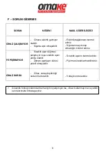
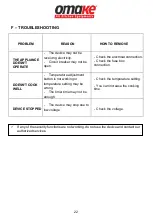
Page 24: ...e may not be receiving electricity Circuit breaker may not be open Check the electrical connection Check the fuse box connection DOESN T COOK WELL Temperature adjustment button is not working or tempe...

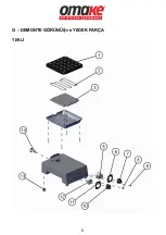
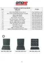
Page 25: ...23 G EXPLODING DRAWING AND SPARE PART LIST SINGLE...

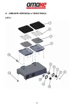
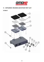
Page 26: ...24 G EXPLODING DRAWING AND SPARE PART LIST DOUBLE...

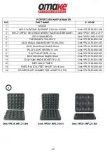
Page 27: ...E 90 250 Omk YPC01 PLS01 007 7 DG01 Small Knob Set 6 Short Omk YPC01 PLS02 002 8 PILOT LIGHT GREEN 10 mm Omk YPC50 ELK08 008 9 PILOT LIGHT RED 10 mm Omk YPC50 ELK08 007 10 DG01 Mini Knob Set 6 Short O...

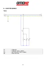
Page 28: ...26 H ELECTRICAL CIRCUIT DIAGRAM SINGLE T1 THERMOSTAT L1 THERMOSTAT SIGNAL LAMP L2 LIMITOR SIGNAL LAMP R1 RESISTANCE 1000W...

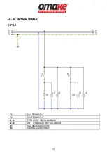
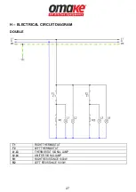
Page 29: ...27 H ELECTRICAL CIRCUIT DIAGRAM DOUBLE T1 RIGHT THERMOSTAT T2 LEFT THERMOSTAT L1 L3 THERMOSTAT SIGNAL LAMP L2 L4 LIMITOR SIGNAL LAMP R1 RIGHT RESISTANCE 1000W R2 LEFT RESISTANCE 1000W...

Reviews: