background image


 Page 

15

 from 

38


TUNE     


Anode capacitor for tuning, tuning of higher frequencies to "0", lower 


frequencies to “100”. 


LOAD               

Output capacitor tunes antenna load resistance to amplifier.


Capacity is low at „100“ and high at "0" on the scale. 


OFF                 

You switch off the amplifier by pressing this button. 


ON                  

You switch on the amplifier by pressing this button. After 3 min. of 


warm-up delay, amplifier will be ready for operation.  


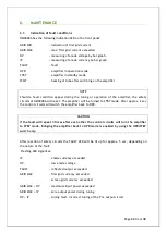
OPR/STBY 


„OPERATE“  sets the amplifier ready for transmit operation. In STBY, if 


WAIT-LED is on or the amplifier is OFF,  the amplifier  is  in bypass-mode 


and  your transceiver is directly  connected  to the  antenna. Maximum 


allowed power in bypass mode is 200W. 


RF OUTPUT    

Bar graph – shows output power . 


REFLECTED POWER 

   Bar graph –  shows reflected power from the antenna.  


Maximum level is 350W otherwise amplifier switches to STANDBY mode. 


Ig2


Bar  graph  –  measures  the  current  of  the  second  grid  from  -80mA  to 

+120mA. 


HV/IP/TUNE

            Bar graph – measure the anode voltage, anode currency or tuning of the    


          amplifier.  


Summary of Contents for X8NOM4000A

Page 1: ...Page 1 from 38 Instruction Manual OM4000A SHORTWAVE POWER AMPLIFIER FCC ID X8NOM4000A WWW OM POWER COM OM POWER s r o 93030 Báč 126 SLOVAKIA Contact 421 905 321 410 e mail om power om power com ...

Page 2: ... 5 Cooling 13 4 6 Remote Control 13 5 OPERATION 13 5 1 Operation Elements 14 5 2 Configuration of Power Amplifier 16 5 2 1 TCVR Support Settings 17 5 2 2 Connection with not supported TCVRs 18 5 2 3 Communication Loss 19 5 2 4 Antenna Switching Menu 19 5 2 5 Bandpass Filter Settings 20 5 2 6 Loading Factory Default Settings 20 5 2 7 Mute Option 21 5 2 8 LCD Settings Menu 22 5 2 9 Operation in Manu...

Page 3: ...nd BPF 31 7 5 of connection USB Micro KEYER II with IC7800 or IC7700 32 7 6 Example of connection USB Micro KEYER II with another ICOM 33 7 7 Example of connection USB Micro KEYER II with YAESU or ELECRAFT 34 7 8 Example of connection PA with MicroHAM MKII MK2R etc CI V output 35 7 9 Controlling the OM Power automatic amplifiers with Flex 36 Radios Series 6xxx 7 10 Block diagram of the OM4000A 38 ...

Page 4: ...tenna switches The possibility to use 2 different antennas within one band or segment 1 2 Specification 1 2 1 Parameters Frequency Coverage Amateur Bands 1 8 29 7 MHz including WARC Power Output 1500W continuous output no time limit Input Power Usually 50 to 70W for full Output Power Input power can not exceed 100W Input Impedance 50 Ohm VSWR 1 5 1 Power Gain 15 dB Output Impedance 50 Ohm unbalanc...

Page 5: ...ors There are couples of LED and bar graph indicators visible on the front panel to inform you about value of some parameters or operation status Bar graph indicators Power output 50 LEDs Reflected power 20 LEDs Ig2 current 10 LEDs Anode voltage anode current tuning 30 LEDs LED Indicators Current at control grid Ig1 2 LEDs WAIT preheating of tube 150 sec STBY standby OPR operation mode FAULT failu...

Page 6: ...hout the upper lid in place DO NOT ATTEMPT TO SHORT OR BYPASS safety switch under upper lid WARNING The OM4000A amplifier can be operated ONLY if both of supply cables are connected WARNING The OM4000A amplifier is neither to be used in a WET or HUMID environment nor to be exposed to RAINFALL WARNING Do not turn the amplifier ON without having connected the ANTENNA or properly rated DUMMY LOAD A h...

Page 7: ...mitigate this disturbance CAUTION Make sure that all screws holding the case together are properly in place and tightened before carrying the amplifier with the handles CAUTION Read this manual carefully Fallow all of instructions during installation and operation to avoid damage to the amplifier not covered by manufacturer s warranty Do not attempt to perform any change of hardware or software 3 ...

Page 8: ...er Supply Board 3 2 Power Supply ower supply of the amplifier is comprised of two of 3 kVA toroidal transformers A soft start is provided using relays and resistors The high anode voltage is made by combining 8 x 420 V total 3360V 2 5A Each has its own rectifier and filter In the high voltage circuit safety resistors are employed to protect the amplifier against overload The source for screen grid...

Page 9: ...er has to be grounded properly Connect the screw on the rear panel of the amplifier to your local grounding system with a copper cable use a cross section of 4 mm2 at least Connect your transceiver to the same grounding system of your shack carefully Use minimum length cables and make certain that the connections are both physically and electrically sound With poor grounding you may risk damaging ...

Page 10: ...uring transmitting the middle pin is connected to the ground The relays of the OM4000A have to be switched earlier than HF is applied cold switching Modern transceivers they have a time delay between PTT switching and power output CAUTION If you are using and older transceiver or transmitters without time delay we recommend to connect the PA in such a way that the transmit receive switch foot swit...

Page 11: ...hen CI V disables RS232 Otherwise selection of interface is done via TCVR type PC DB 9 RS232 port is used for communication with your PC Please use setting you would normally use if using direct TCVR PC connection ALC RCA Phono Automatic Level Control is used when tuning the PA to block drive level BYPASS COM Connector 5 5 2 1mm allows you to connect an external 12V DC power supply rated at 200mA ...

Page 12: ...ctors as described below PIN OUT 1 ALC Out 2 NC 3 INHIBIT Control voltage 4 TX INHIBIT for Yaesu and Elecraft this supersedes ALC output 5 NC 6 KEY OUT 7 NC 8 KEY IN 9 15 GND ANT BPF SW DB 25 is used for switching of external HP BPF or external Antenna Switch Maximum switching of 30V 0 5A is possible PIN OUT 1 antenna port 1 2 antenna port 2 3 antenna port 3 4 antenna port 4 5 antenna port 5 6 ant...

Page 13: ...air intake and exhaust areas of the PA The centrifugal blowers provide the necessary cooling of the amplifier even during long contests The main blower is activated by switching the PA on and it is turned off when cooling is finished approx 1 5 min after switching off the PA depending on the temperature of the tube The supplemental fan is turned on depending on the temperature of the air exiting f...

Page 14: ...ace to a warm one because not visible condensation may develop and this could result in damage to the high voltage circuits of the PA CAUTION Never try to change antenna output during a transmission to avoid warranty loss NOTE When you decide to have a short operating break place the amplifier in the standby mode rather than switch it off 5 1 Operation Elements There is couple of operational eleme...

Page 15: ...operation OPR STBY OPERATE sets the amplifier ready for transmit operation In STBY if WAIT LED is on or the amplifier is OFF the amplifier is in bypass mode and your transceiver is directly connected to the antenna Maximum allowed power in bypass mode is 200W RF OUTPUT Bar graph shows output power REFLECTED POWER Bar graph shows reflected power from the antenna Maximum level is 350W otherwise ampl...

Page 16: ...last used antenna on a given frequency SET button for MAIN MENU Confirmation of selection Saving of selected value Saving of tuning parameters TUNE Push button for selection of TUNE mode AUTO Push button for selection of AUTOmatic mode MAN Push button for selection of MANUAL mode DWN UP Push button for selection of band segment or parameter 5 2 Configuration of Power Amplifier hen the ON button is...

Page 17: ...nsceivers ICOM ELECRAFT KENWOOD TEN TEC ORION YAESU Press SET button and scroll UP DWN to CHOOSE TCVR mmm Confirm CHOOSE TCVR by pressing SET again and scroll UP DWN to your transceiver type Confirm the selection by pressing SET mmm Continue by selecting Baud Rate Press SET button and scroll using UP DWN to BAUD RATE Press SET again Baud rate for TCVR PA communication is shown on the display ...

Page 18: ... display 5 2 2 Connection with not supported TCVRs For communication with TCVRs that are not supported by OM4000A for example JST 245 and older types of Kenwood an external IF 232 converter is to be used You can also use devices from several companies that produce compatible CI V output which deliver frequency information in ICOM format through the CI V output Then the PA will be connected in the ...

Page 19: ...2 4 Antenna Switching Menu If you have 3rd party external antenna switch connected to your amplifier i e MicroHAM TEN SWITCH you need to configure the assignment of each port to a specific band or antenna mmm Example of Communication loss message mmm By pressing SET and scrolling to ANTENNA SETTINGS and confirming by SET you get current band and its antenna selection mmm By scrolling UP DWN you ca...

Page 20: ...press SET and scroll using UP DWN to LOAD DEF VALUES and confirm by SET mmm Then select how many antennas you want per current band 1 or 2 and always confirm your selection by pressing SET mmm By scrolling UP DWN you assign which PORT is used on your external antennas switch for this particular antenna ANT 1 ON PORT 01 Shall you decide to use 2 antennas for this band then after confirming that wit...

Page 21: ...ant to notice that this is not a true ALC only the transmitter will be blocked in this way during the process of PA tuning 5 2 8 LCD Settings Menu Then select if you want to erase all settings pressing TUNE or just one setting value SET button In the case of resetting a single parameter use UP DWN to select which option and confirm by SET Using SET and scrolling UP DWN select SET MUTE and confirm ...

Page 22: ...is purpose the amplifier has to be tuned carefully T Using SET and scrolling UP DWN select SET LCD CONTRAST and confirm it by SET By pressing Up or DWN you can vary contrast of the LCD display Finally press SET to confirm selected value To enter Manual mode of the PA press MAN By pressing MAN repeatedly you select BAND and band segment You can control the segment or band by scrolling the UP DWN bu...

Page 23: ...nt will be shifted and IM products will be rapidly increased If a value of 100mA is exceeded the safety devices will switch the amplifier to STBY mode 5 3 1 AUTO or MANUAL There are two possibilities of operation mode in OM4000A AUTO or MANUAL Normally when you are using CAT interface connection between TCVR and PA in AUTO mode PA will tune automatically to the TCVR frequency If you do not have or...

Page 24: ...eters are not very good and input power is higher than 15watts safety devices will switch PA automatically to STBY In such a case start with step 4 go thru all next steps 4 Reduce the power output of your transceiver to the minimum 5 Switch OPR STBY to OPR position OPR LED lights up 6 Choose the TUNE position of multimeter 7 Transmit and increase driver power to cca 10W CAUTION If the input power ...

Page 25: ...s or TUNE LOAD values Be sure that VSWR is not higher than 2 1 and input power is LOW After excluding possible human mistakes you will be able to work for long time with this amplifier 5 3 3 Tuning Adjustment Entering the TUNE mode is done by pressing the TUNE button The OM4000A then switches the transceiver to RTTY and sets the frequency to corresponding segment By changing the values of TUNE and...

Page 26: ...e amplifier will be turned to STBY mode After approx 2 sec the control circuits will switch the amplifier back to OPR CAUTION If the fault will repeat 3 times after each other the control circuits will turn the amplifier to STBY mode Bringing the amplifier back to OPR mode is enabled by using the OPR STBY switch only After reaction of safety circuits the FAULT LED will be lit up for approx 5 sec d...

Page 27: ...cement In the case of vacuum tube damaging contact the manufacturer or your dealer for ordering new one You will get instructuions how to change tube and how to preset proper parameters too Be very careful you will do it only on your own risk If you are not comfortable to replace vacuum tube itself contact your Service Center please 6 4 Cleaning To prevent damage of amplifier surfaces and plastic ...

Page 28: ...Page 28 from 38 7 1 ...

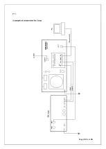
Page 29: ...Page 29 from 38 7 2 Example of connection for ELECRAFT ...

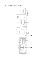
Page 30: ...Page 30 from 38 7 3 Example of connection with Yeasu ...

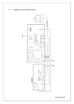
Page 31: ...Page 31 from 38 7 4 Example of connection with antenna switch and BPF ...

Page 32: ...Page 32 from 38 7 5 Example of connection USB micro KEYER II with IC7800 or IC7700 ...

Page 33: ...Page 33 from 38 7 6 Example of connection USB micro KEYER II with another Icom ...

Page 34: ...Page 34 from 38 7 7 Example for connection USB micro KEYER II with Yeasu or ELECRAFT ...

Page 35: ...Page 35 from 38 7 8 Example of connection PA with MicroHAM MKII MK2R etc with CI V output ...

Page 36: ...omatic amplifiers with Flex Radios Series 6xxx Download and install the software for rerouting the serial ports for example DDUtil http k5fr com DDUtilV3wiki index php title Download In Setup Features set conenction for Flex radio for example on COM4 ...

Page 37: ...ough USB RS232 adapter Amplifier connect to redirected port COM2 and on OM4000A into set up menu choose TCVR Kenwood and 9600baud rate NOTE This was just one of more connection possibilities with FLEX RADIO SERIES 6XXX NOTE For the connection between PA and FLEX Radio use null modem serial cabel ...

Page 38: ...13 K6 K3 K2 K4 P13 K2 K3 Kl 8 Kl 7 K1 Kl 3 Kl 4 Kl 2 Kl 1 K5 K4 K1 K2 K3 K5 TR2 TR1 AC14V AC2 AC1 K4 Cover SW OM 4000A Block diagram HF PROBE Fuse Blower SW ON BOARD HV SUPPLY CONTROL BOARD DISPLAY BOARD OUTPUT AC 2 AC 1 INPUT METER SW STBY SW PWR METER SCREEN BOARD INPUT BOARD J 1R0 R9 2 1 J 1R0 R8 2 1 2 1 2 1 2 1 2 1 2 1 X2 FU728f 7 5 4 3 2 2 1 1 2 X1 FU728f 7 5 4 3 2 1 2 2 1 2 1 2 1 2 1 2 1 2 1...

Reviews: