OM POWER OM1006 Instruction Manual Download Page 24

24

Overdriving error

“ appears. Decrease the input power under maximum driving level, set

OPER mode again to continue transmitting.

When one half of the double MOSFET will be broken for example, or some fault in the output
circuit presents, output power of the PA will decrease rapidly. Fault message „

Gain is too

low

“ appears, amplifier will stay in OPER mode, but transmitting will be blocked. In this

situation contact the manufacturer for the assistance.

In the case of the main power supply failure, when voltage drops below 42 volts, fault
message „

Voltage is too low

“ appears, the amplifier will stay in operation mode and

transmitting will be blocked. You have to check inside fuse first. If fault persists, contact the
manufacturer or your dealer for the assistance.

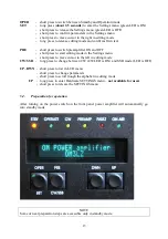
When the amplifier reaches inside temperature of 70 deg. Celsius, warning message

Amplifier is too hot

” appears on the display. At 75 degrees protection circuit will

automatically  block  transmitting  (fault  condition).  You  have  to  decrease  the  power  or  wait
couple of minutes to be ready transmitting again.

When current of the PA exceed the limit value,  „

Current is too high

“ fault message appears

on the display, amplifier will stay in operation mode and transmitting will be blocked.
Decrease input power first and try to transmit again. If this will not help and current will stay
high, contact the manufacturer for assistance.

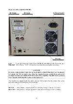
If you turn the power amplifier ON and no LED will be illuminated, display stays dark, check
mains first, and then check fuses inside the PA (see next part for more details).

CAUTION

If  MOSFET  is  destroyed,  do  NOT  attempt  to  replace  it,  in  any  case!  Contact  the
manufacturer immediately.

WARNING!

Never try to change or move any part inside the amplifier except of internal fuses.
Substitution of parts may void intrinsic safety!

6.2.

Fuse  Replacement

There  are  two  fuses  installed  inside  the  OM1006  power  amplifier.  They  are  located  on  the
supply board on the left hand side of the PA, above the main power supply. The user

is

allowed

 to change these fuses.

WARNING!

Before opening the upper lid of the amplifier make sure that power supply has been
disconnected.  Take out power cord from the outlet!

OM1006 uses one fuse 10 Amps „T” type 5 x 20 mm for main 50V DC power supply and one
fuse 500mA „T“ type for small 12V DC power supply.

Summary of Contents for OM1006

Page 1: ...Instruction Manual OM1006 Solid State 50 MHz Power Amplifier OM POWER s r o 930 30 B 126 SLOVAKIA E mail om power om power com...

Page 2: ...ON 6 3 1 HF part 6 3 2 Power Supply 8 3 3 Safety Devices 8 4 INSTALLATION 9 4 1 Grounding 9 4 2 Coaxial Cable 9 4 3 Control Cable 9 4 4 Main Supply 11 4 5 Cooling 11 5 OPERATION 11 5 1 Operation Eleme...

Page 3: ...SB No 1 18 5 2 2 6 Bias CW No 1 18 5 2 2 7 Software version 19 5 2 3 Operating mode 19 6 MAINTENANCE 23 6 1 Indication of Fault Conditions 23 6 2 Fuse Replacement 24 6 3 Cleaning 25 7 APPENDIX 26 7 1...

Page 4: ...000W SWR protection Automatic switching to STBY when reflected power is 100W or higher Intermodulation distortion 32 dBc Suppression of harmonics 60 dBc MOSFET MRFE6VP61K25HR6 Cooler 3 axial fans 2 ax...

Page 5: ...the right in edit mode Settings menu PRE Preamplifier ON Edit mode start cursor to the left in edit mode CW SSB mode switch OSD Indicator 140 x 16 dot graphic display to view Display menu Settings men...

Page 6: ...e installed in such a way that the rear panel will stay accessible CAUTION The amplifier is an A category product In a household it can influence other electric appliances In such cases the user is to...

Page 7: ...red impedance level and the length of the coax was tuned to achieve maximum efficiency and maximum power transfer between the device and its load impedance Top view on the opened OM1006 Input Output R...

Page 8: ...external source of AC in the range from 100VAC to 250VAC 50 or 60 Hz It can be powered by a portable generator for example Switch Mode Power Supply and the Supply Board Two fuses are visible 3 3 Safet...

Page 9: ...you may risk damaging to your equipment having problems with TVI BCI or your transmitted signal may be distorted 4 2 Coaxial Cable The output of the transceiver is to be connected to the input of the...

Page 10: ...we recommend to connect the PA in such a way that the transmit receive switch foot switch for example is connected with the KEY IN socket of the amplifier The KEY OUT socket is to be connected with th...

Page 11: ...e activated when inside temperature exceeds 40 deg Celsius Their speed is gradually rising with increasing temperature Two fans inside the power supply start to operate depending on the current drawn...

Page 12: ...ty loss 5 1 Operation Elements There is couple of operational elements accessible or visible on the front panel STBY Standby mode LED OPERATE Operation mode LED CW CW mode LED PREAMP Preamplifier ON L...

Page 13: ...s to start editing mode in the Settings menu short press to move cursor to the left in editing mode CW SSB long press to change between CW CW LED is ON and SSB mode LED is OFF UP DWN short press to li...

Page 14: ...es using UP DWN buttons UP for upper line scroll DWN for bottom line scroll OM POWER amplifier Own text Bar graph for output power PWR in watts short bar graph PWR in watts REF in watts PWR in watts S...

Page 15: ...tton s corner will light The top line will display Settings menu in the bottom line user can scroll these parameters or texts Own text Display delay Bias delay Preamplifier delay Bias SSB No 1 Bias CW...

Page 16: ...etc Maximum 20 characters When you finish editing press the SET button for about 2 5 seconds to confirm new text and to leave editing New text replaces the original Own text in the Display Menu 5 2 2...

Page 17: ...uch a case bias value after pressing the PTT will depend on the working mode Settings menu appears in the upper line Select Bias delay in the bottom line To open edit mode press PRE Use UP DWN buttons...

Page 18: ...econd line about 2 7A Do not leave this status active long time Use the SET button to release checking 5 2 2 6 Bias CW No 1 This parameter will be checked without the possibility to change it When Set...

Page 19: ...lowed power in bypass mode is 100 Watts Passing RF power is not measured or displayed if PA is either in standby mode or turned OFF Push the OPER button to activate operation mode At that moment 50V D...

Page 20: ...T for the first time set the RF power in your transceiver to the minimum from 1 to 3 watts Select parameters in the Display menu as is visible in the previous or next picture and press PTT You can che...

Page 21: ...173W Power gain from input to output of the PA was 23 5 dB When operation mode of the PA was changed from CW to SSB output power increased TCVR output power remained the same This is because the oper...

Page 22: ...mportant parameters of PA Do not exceed the output power of 1000 watts in CW operation mode and about 800 watts in SSB AM FM and digi operation mode even if more is reachable NOTE We recommend using t...

Page 23: ...display the amplifier will stay in the operation mode but transmitting will be blocked Decrease the input power to allow transmits again When reflected the power of the PA exceed 100 watts Reflected...

Page 24: ...tting again When current of the PA exceed the limit value Current is too high fault message appears on the display amplifier will stay in operation mode and transmitting will be blocked Decrease input...

Page 25: ...fier surfaces and the plastic components do not use aggressive chemicals for cleaning Do not open the amplifier for cleaning Outer surface may be safely accomplished by using piece of soft cotton clot...

Page 26: ...26 7 APPENDIX 7 1 Block Diagram of OM1006 Power Amplifier...

Reviews: