53
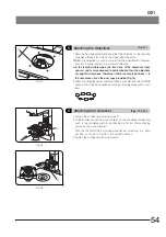
Fig. 70
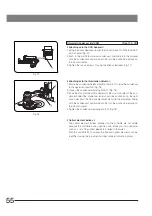
Fig. 71
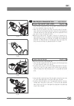
Fig. 72
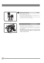
Fig. 73
<<
Attaching the Scales
>>
}Scales for use with a 96-well microtiter plate are provided with the me-
chanical stage.
1. Loosen the two clamping knobs
6
at the top of the stage’s X-axis guide.
Positioning the scale numerals correctly, plate the X-axis scale
7
on the
guide. Then tighten the clamping knobs. (Fig. 70)
2. Positioning the scale numerals correctly, plate the Y-axis scale
8
on the top
of the stage’s Y-axis guide. The scale will be held in place magnetically.
(Fig. 70)
<<
Attaching the CK2-SS Substages
>>
· These plates can be attached in the same way as outlined in
Mechanical
Stage (IX-MVR)
above.
}When the mechanical stage is not used, stage extender plates
9
can be
attached at both sides of the plain stage. (Fig. 71)
Stage (IX2-SFR)
(Figs. 72 & 73)
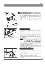
1. Insert the stalk
2
of the flexible X-axis/Y-axis knobs into the U-shaped
notch on the positioning bracket @.
2. Using the Allen screwdriver, tighten the clamping screw
3
of the bracket
lightly to the stage.
3. Align the stage’s center alignment index line
4
with the edge
5
of the
upper stage. (Fig. 73)
4. Slide the positioning bracket to and fro in order to determine the most
convenient stalk angle.
5. Tighten the bracket’s clamping screw firmly.
Mechanical Stage (IX-MVR)
· This is attached in the same manner as outlined in
Stage (IX2-SFR)
)
above. The mechanical stage, however, is not provided with a stage center
alignment index line. Instead, rotate the Y-axis knob until the position D or
E on the Y-axis scale is reached to bring the stage into the center.
6
7
8
9
1
2
3
5
4
<<
Attaching the Positioning Bracket
>>
}A flexible stalk for the coaxial X-axis and Y-axis knobs is employed with the
IX2-SFR stage and IX-MVR mechanical stage. These stages are provided
with a positioning bracket that allows the tilt of the stalk to be adjusted to
suit the observer’s preference.


