


162
Chapter 8 Storage and maintenance
8.2
Replacing the battery
DANGER
•
Before opening the battery cover, press the [POWER] button to turn off the power (the
POWER indicator turns off). Not doing so may cause an electric shock.
WARNING
•
Be careful not to injure yourself when replacing the battery.
•
Never use a battery other than the one designated by Olympus. Otherwise, failure of the
instrument may not only lead to a malfunction but also a fire.
•
Be careful not to leave any foreign objects in the battery compartment when replacing the
battery. Otherwise, a fire or malfunction may result.
CAUTION
•
Be careful not to accidentally drop the battery during replacement.
•
If the battery inlet is pointed upward, the internal battery may not come out.
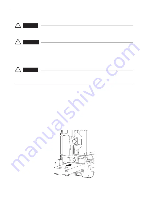
Replacing the battery
1
Press the [POWER] button on the base unit to turn off the power
(the [POWER] indicator goes off).
2
Loosen the battery cover screws to open the battery cover.
3
Open the claws on the battery inlet until it clicks, and the battery
will come out.
4
Grasp the battery and remove it.
5
See “Supplying power from the battery” (page 36) for information
about putting in a new battery.
Summary of Contents for IV8000-2
Page 2: ......
Page 10: ...2 2 Rating plate B 3 LCD monitor warning plate...
Page 206: ...198...
Page 207: ......


