
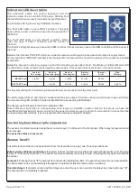


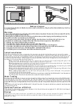

Access level 2:
Includes all the functions that the user can do and an access code is required. The code is
"34”
, it is the same for all
panels and can
not be changed. The functions that can be implemented using this code are the following:
Evacuate:
Gives evacuate signal to the panel.
The user must enter the
user code
( 34)
and then the key
s
'4'
and
'4'
.
Then the panel will go to alarm state.
The sirens
will
sound and
the internal buzzer
also
.
Siren Silence:
When an alarm is issued and we want to silence the sirens then we must enter the user code
( 34 )
and then the keys
'5'
and
'5'
. The sirens are silenced but the internal buzzer continues to sound.
The panel remains
in normal operation. A new alarm from another zone will resound the sirens.
To resound the sirens press again the same
code.
Panel Reset:
When an alarm or fault condition has occurred and we want to reset the panel we must enter the user code
(34)
and then the keys
'5'
and
'6’
. The panel lights all LEDs in sequence and then enters normal operation.
Zone enable/disable:
If we want to disable the operation of specific zones then we must enter the user code
( 34 )
and then the keys number
'5'
and
'4'
. The LED marked 'General disable' start to blink, and if a zone is disabled the
corresponding '
Fault
' LED lights to indicate this. Using the keys 1, 2, 3, 4, 5 and 6 we can enable or disable the respective
zones. The disabled zones light the corresponding LED. The panel exits this mode if no key is pressed for more than 30
seconds. The panel then conducts an automatic RESET and enters normal operation mode.
D
isabled zones
does not
give alarm or fault condition.
If we have disabled zones then this is indicated with the indicators 'General disable' and the
corresponding Disable LED zone and the buzzer sounds once every minute.
Siren enable/disable:
If we want to disable the operation of specific sirens we must enter the code
(34)
and then the
keys
'6'
and
‘6’
. The LED marked 'General Test' start to blink, and if a siren is disabled Siren1 LED lights for siren 1 and
Siren2 LED lights for the siren 2. Using the keys 1 and 2 we can enable or disable the respective sirens. The disabled
sirens have a LED lighted. The panel exits this mode if no key is pressed for more than 30 seconds. The panel then
conducts an automatic RESET and enters normal operation mode.
All disabled sirens are supplied with the proper
voltage but the panel can not enable them or read their condition.
If we have disabled sirens then this is indicated with the
indicator 'General disable' and the buzzer sounds once every minute.
Delays ON/OFF:
If we want to
disable the delays of the outputs. We must
enter the code
(34)
and then the keys
'6'
and
‘4’
.
Then the delays will be disable, the LED
marked
“Delays ON” will turn off. To enable the delays we must press again
the code.
Page 3 from
10
921163600_09_020
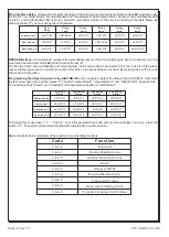
Access level 3:
These functions are implemented during the installation and need the technical code to be accessed. The technical code is
"364"
, it is the same for all panels and can
not be changed. These functions can be implemented using the technical code
are activation methods used for the relays and can be done only if the panel has not issued an alarm or fault condition.
These functions are ancillary and not required by the EN 54-2.These methods of programming are:
AUX RELAY programming:
If we want to program the operation behaviour of the AUX RELAY we must enter the technical
code
( 364 )
and then press the key
'5'
. The 'General fault' and 'General alarm' LEDs start to blink. The Alarm
zone
LED
s
and the fault LED zone
show the way the AUX RELAY .
If the Alarm led of the zone is on then we have logic AND for the aux
relay activation. If the fault led of the zone is on then we have logic OR for the aux activation.
For example if Alarm Zone 1 and 2 is on and Fault Zone 3 and 4 is on, then the relay will be activated when Z1 and Z2 is in
alarm condition or Z3 or Z4 are in alarm condition
To change the state of each zone, press the corresponding number each time.
In order to exit this programming mode and to store the settings in memory do not press any key for more than 30 seconds.
This system will conduct an automatic RESET and will enter normal operation mode.


