
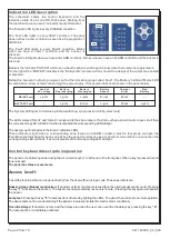


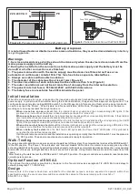

Indication LED description
The schematic shows the control keyboard and the
indication plate of a 6 zone BS-
1
636 panel. Starting from
the top left side we can see 4 indicators marked 'General'.
The 'Disable' LED lights in every DISABLE condition.
The 'Test' LED lights in every TEST condition .The panel
does not ha
ve a
test condition as specified in
paragraph
11
of EN 54-2.
The 'Fault' LED lights in every FAULT condition. Blinks
when we have a FAULT
condition
and the buzzer is
silenced.
The 'Alarm' LED lights when we have an ALARM condition. Blinks when we have an ALARM
condition
and the buzzer is
silenced.
Below is the indicator “POWER” which is on when the panel is working and blinks when there is mains supply failure.
On the right of the “POWER” indicator is the “Delays ON” indicator which shows if the delays of the output are enabled
or disabled.
Below the `General` indicator group we can find the indication group called `Fault`. The 'Batt
ery
' LED and '
Mains
' LED
in combination, show us faults concerning the power supply. These combination
s
are shown in the panel below.
BATTERY Fault
MAINS Fault
Lack of
AC voltage
Battery
Overcharging
Battery
Discharged
Battery
Absent
Charger
Error
Lights
----
Lights
Lights
Lights
Blinks
Blinks
Lights
Blinks
Blinks
The '
System
LED lights to indicate a problem with the main processor unit (System fault).
The LEDs marked 'Siren1' and 'Siren2' correspond to the siren outputs. If a siren out has a short circuit or open circuit then
the corresponding LED will blink. If a siren is disabled the corresponding LED will light.
The next group of indicators is the 'Alarm' indication LEDs.
These indicators light when a corresponding zone issues an ALARM condition.
Next to
this group we have the
'Fault/Disable' indication for each zone. When the panel monitors an open or short circuit condition in a zone then the
corresponding LED will blink. If a zone is disabled the corresponding LED will light.
Control keyboard description/operation
The panel is controlled/ operated using the six numeric keys (1 to 6) found on the front panel. When a key is pressed a short
tone is issued.
The panel has three access levels.
Access level 1:
has all the functions that can be done directly from the user without using a code. These operations are:
Buzzer silence / Buzzer reactivation:
If an alarm of fault condition is issued then the internal buzzer will sound. Pressing
the key
"1"
will silence the buzzer.
( The buzzer sounds periodically once every minute.) Pressing this key again will reactive
the buzzer.
Lamp test:
Pressing the key
"2"
a lamp test is conducted by lighting the LEDs. The panel then returns to normal operation.
The above tests can be conducted only if the panel is in quiescent state (No fault or alarm conditions).
Override Delays:
If an alarm
occurs and the delays are active the user can overrride the delays by pressing the key
“4" .
The output will be immediately activated.
Page 2 from
10
Bad
Battery
----
Lights
921163600_09_020


