

Page 4 of 5
3. USB GATEWAY
To keep data organized, you are advised to create a spreadsheet of the wireless network(s) including
SID, RF Channel(s), NKey(s), IP Addresses (if any), UID's of the devices per network, etc. Create a
profile for each of the existing wireless networks, by clicking
“Profiles”
. Enter SID, RF Channel and
NKey and then click
“Add”
to add a wireless network profile into memory. If you want to delete a profile,
select the entry within the dropdown list below and click
“Delete”
. Close the window when you have
finished entering the profiles. In order to scan a wireless network for
“not hosted”
wireless devices,
enter the SID, RF Channel and NKey parameters of this network, in the top area of the main window and
click on
“Scan”
. In the meantime, if there are other Network Masters (Gateways) transmitting with the
same parameters, you will have to deactivate them to avoid data collision. In most cases, the wireless
devices are on factory default parameters (SID=00000001, RF Channel=2, NKey=00000000). Within
the first 5 minutes the wireless devices will appear on the list. If you are missing any, click on
“Re-Scan”
button to scan again. To apply new settings on an entry, right click on it and select one of the previously set
profiles. You can apply different profiles to other wireless devices. To apply a profile into multiple entries
quickly, you can use the copy-paste functionality with
“Ctrl+C” / “Ctrl+V”
keys within the
“Parameters”
cell. To apply the selected profiles into the selected devices, click
“Change Network”
button. The
procedure might take a while to finish (20' per 100 selected). The
“Phase”
column indicates the progress
for each unique selected device.
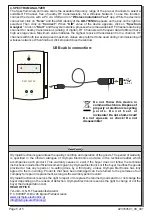
This mode sets the
GR-7605/V2
as a Gateway of a Wireless Network. To enable this mode, connect the
device to the master PC running
software via USB. The device is detected by the system and is
Phos4.0
automatically registered as a
Gateway
. Active wireless devices that operate with the same wireless
parameters (SID, RF Channel and NKey) will be detected by the Gateway. You can change the
parameters of the Gateway (e.g. to default) by editing the Gateway under “Wireless Devices > Gateways”
tab. Then proceed into network configurations (according to the Commissioning Guide).
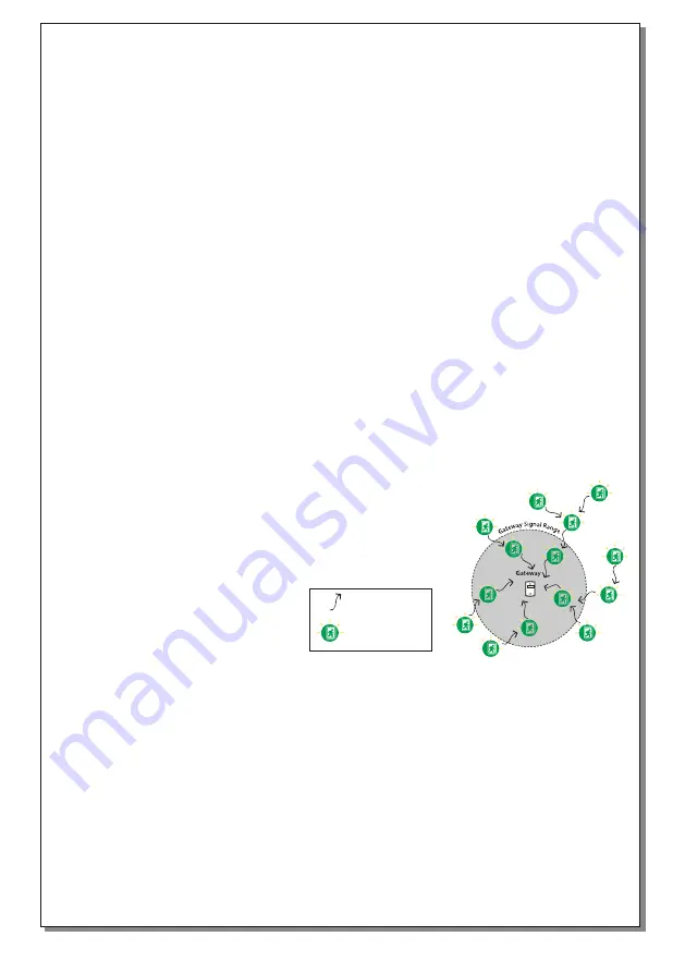
IMPORTANT:
A single USB Gateway can support up to 200 connected wireless devices. Only one
Gateway can exist in a Wireless Network. Multiple nearby Wireless Networks can co-exist, when
separated by SID value. It is recommended to use different RF Channels for neighbor wireless networks
when available.
Signal route
Wireless luminaries
USB
LOW
CUT
SYS
CHA
RF
I
III
II
IIII
IIIII
RSSI TESTER
923760501_09_001


