


Page 2 of
5
Auto power-OFF:
• 10' of inactivity
Upper LED indications:
Every time the device is activated, it will start with SYSTEM indication LED mode. In this indication
mode, the power status of the device is indicated. While on SYSTEM indication LED mode:
•
USB :
USB powered (red LED) ON when the device is connected to a USB port.
charged and USB is connected.
•
CUT :
Cutoff pending (green LED) When ON, the device will be powered off within the next 10
•
CHA :
Charger on (yellow LED) ON when the battery is charging. OFF when battery is fully
seconds. Always off when the device is normally operating.
indication LED mode.
•
LOW :
Battery low (yellow LED) ON when battery is depleted. Always OFF when USB powered.
•
SYS :
S
ystem LED mode indicator (green LED) Blinks 1 time per second when on SYSTEM
The device will automatically shut down for one of the following reasons:
• Battery is depleted (warning LED “LOW” will be lit previously)
When power-OFF function is initiated, the LED “CUT” will be lit for 10' before shut down.
The GR-7605/V2 will never power off when being connected to USB port.
Button functions:
• Long press (>3s): Power-ON or OFF the
(only when powered from battery - RSSI
GR-7605/V2
Tester)
In order to power-OFF the device, press and hold the button until the LED “CUT” is lit.
LED “CUT” indicates pending cutoff, a function which shuts down the device to preserve power.
The prolonged button press activation prevents powering-ON unwillingly.
•
Short press (<3s): Switch between SYSTEM and RSSI indication modes (RSSI Tester)
1. RSSI Tester:
Signal Strength Tester (RSSI) mode is used to check the received signal level at any position of the
installation area, before installing a wireless device (wireless luminaire, wireless network extender
etc.). There are 7 LED indicators on the front of the device. Two LEDs are located at the lower part
(RF and signal markings) and the remaining 5 are hidden behind the semi-transparent opening on the
upper part of the device. These hidden 5 LEDs are performing in two different modes: System mode
and Signal Level mode. In order to check the signal level (or RSSI), the Signal Level mode is used.
Swapping between modes is done by clicking the multifunctional button. The device is powered by a
Ni-MH 3.6V/240mAh rechargeable battery, which gives at least 2 hours of autonomy when fully
charged. The battery is non-replaceable. When connected to USB, the battery will be charged with a
maximum current of 60mA approximately. 5 hours of charge will achieve at least 90% of full charge.
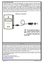
POWERING ON-OFF THE DEVICE
Power on the device by holding down the power button for at least 2 seconds, until the cutoff indication is
gone. To power off the device, hold down the power button for at least 2 seconds until cutoff indication is
lit. Then after a few seconds the device will power off. While the device is USB powered, it will never
power off. Power off is possible only when the device is battery powered. While the device is inactive, no
power is drawn from the batteries.
- The button is pressed for more than 2 seconds, until the CUT indication is lit.
- Empty battery. An indication of low battery is followed by an automatic power off after a few minutes. So
a LOW LED indication will not be instantly followed by power off.
- Auto shutdown. To avoid unintended battery discharge, the device will power itself off, after 10 minutes
of button inactivity. Auto shutdown is inactive when USB powered.
SWITCH BETWEEN INDICATION MODES (SYSTEM - LEVEL)
In order to power-ON the device, press and hold the button until the LED “CUT” is not lit.
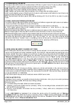
When used as a Signal Strength Tester, this device has 2 different indication modes for LED bar.
Switching between SYSTEM and SIGNAL LEVEL indications is achieved by a short press of the button.
While in SYSTEM mode, the far right green LED will blink continuously. While in SIGNAL LEVEL mode,
the far left red LED (very low, or no signal) will always be lit and the other 4 LEDs will fill a “signal level
graph” in accordance with the RSSI.
The device will power off for the following reasons:
USB
LOW CUT
SYS
CHA
923760501_09_001


