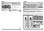
LED MODULE CHARACTERISTICS
Olympia Electronics S.A
.
65 °C max. across the board
2,8-2
,
9V DC
3-3,1V DC
1W
2
W
0405183
GR-4
90
/WP
GR-4
9
1/WP
GR-4
9
2/WP
GR-4
9
3/WP
NOTE:
LED= Light Emitting Diode
LABELING EXPLANATION:X:
Self contained
0:
Non maintained
(*)
A:
Including test device
E:
With non-replaceable lamp(s)
F:
Automatic test gear complying
with IEC 61347-2-7 denoted EL-T
90:
1.5 hour duration
180:
3 hours duration
(*)
Non Maintained operation: The luminaire turns on illumination source,
only in case of power supply
failure.
fixed connection between main pcb and led module
TEST
A-1900
Test
and
Faults R
eset operations with the A-1900 card (not
included and available
after
request).
For
lights
test, you
must place the card in front of the TEST indicator and remove it
immediately. For
Autonomy Test
, you must place the card in
front of TEST
and
hold it for 5 to 10 seconds.
To reset errors
you must place the card in front of TEST by
holding it for
10
to 1
5
seconds and removing it.
923493000
_0
9
_003
Page
6 from
7
Battery replacement
It can be done only by a competent person and after the mains interruption
.
1. Detach the front cover by applying pressure using a flat blade screw driver. Next, unfasten the four
retaining screws without removing them and remove the diffusor.
3
. Disconnect the connector and remove the old battery.
4
. Connect the new battery with the same type (step
2
of the installation
instructions
) and place it in
the position of the old one.
5
.
Replace the removed parts
and power the device.
Manufacturer
Model Number
Voltage Range
Connections
Nominal Power
Temperature (tc)
CAUTION
:
Do not view directly with bare eyes
Note!! If a module will be used (except the fault
relay module), then t
he installer should fill in
, on the
specification label,
the letter
s
B C
.
X
0
8
1
0
A
E F
The light source of this luminaire is not replaceable when the light source reaches its end of life
the whole luminaire shall be replaced.
ATTENTION!!!