Olsen OMGC-8D Installation, Operation & Maintenance Manual Download Page 25

25

17 - EQUIPMENT AND OPTIONAL ACCESSORIES 
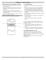
EXPANSION TANK

Expanding water flows into expansion tank. Tank should 

be correct size. Tank is filled with air. As water expands it 

compresses air in the tank to form air pressure cushion. 

This “spring-like” cushion serves to maintain correct 

operating water pressure regardless of water temperature. 

This assures “full measure” of water, even in highest 

radiation unit of system. It also prevents blowing off of 

safety relief valve. Air in tank in beginning (with system 

filled with cold water) is sufficient for proper operation. 

Tank also serves as trap for excess air in system. Air 

would cause gurgling in pipes and in efficient circulation in 

radiators if left in system.

It is possible for tank to become “waterlogged” (filled with 

water). It can also become overfilled with air. This can hap

-

pen after filling system with new water. Fittings provided on 

tank and in line to tank are for bleeding off excess water or 

air. 
When installing this tank, it is important: 

1. 

Tank be higher than boiler top. 

2. 

Pipe to tank continuously rises up to tank (so air 

can “bubble” up to it). 

DIAPHRAGM TYPE EXPANSION TANK

Diaphragm type expansion tank takes place of conventional 

expansion tank. Carefully read instructions packed with 

your tank assembly. 
Tank comes with 10-12 pounds per square inch air charge. 

This is the same as pressure produced in system by 

automatic fill valve. When system is first filled, tank will 

contain little or no water. 
As water is heated its pressure increases. It expands into 

tank, compressing air in tank. Compressed air cushion 

permits water in system to expand as temperature 

changes. Diaphragm type tank can be mounted on air 

purger fitting or at any convenient place in supply or return 

line.

AIR ELIMINATING FITTING (AIR PURGER)

Air purger is used to remove excess air from system. It 

is installed in supply line. It will eliminate air from water 

before it reaches radiators and bleed off this air.

MAIN AIR VENT FOR DOWN FLOW SYSTEMS OR 

DIAPHRAGM TYPE EXPANSION TANK

Before system is filled with water, there is air in pipes and 

radiation units. Some of it will be trapped as system is 

filled . It is possible to eliminate most of this air through 

air vent on radiation units. Main air vent will speed and 

simplify this. Install on highest point in supply main when 

all radiation is below top of boiler. 

AUTOMATIC FILL VALVE

For a safe, efficient operation, hot water system must be 

completely filled

 with water. Adding new water, when 

needed can be done manually (by use of hand valve in 

water supply line). Requires regular attention to system’s 

needs. Automatic fill valve accomplishes this without atten

-

tion. Install in supply line on hot water boilers only. Valve 

operates through water pressure differentials. It does not 

require electrical connection.

DRAIN VALVE

Manual valve provides means of draining all water from 

boiler and system. It is often installed in 3/4” tapping at 

bottom of end boiler section. Or it can be installed in tee 

where return line enters boiler.

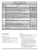
WATER TEMPERATURE CONTROL

Water temperature limit control in relay is adjustable
and may be set as necessary. It may be set as low as 

104°F (40°C), or as high as 220°F (104°C). This depends 

on type and amount of radiation involved and weather 

conditions.

CIRCULATING PUMP

Every forced hot-water system requires circulating pump. 

Separate pump or zone valve is required for each zone, 

if you have a two or more zone system. Pump must have 

capacity to provide circulation required by your system. 

Pump is connected into main just ahead of boiler. It is also 

wired to electrical system.

VENT DAMPER

This product is automatic, motorized stack damper 

developed to increase efficiency of heating system by 

reducing standby losses from heating apparatus and 

conditioned air space. Damper closes chimney vent 

when burner is off and fully opens it when combustion is 

required.

Summary of Contents for OMGC-8D

Page 1: ...INSTALLATION OPERATION MAINTENANCE MANUAL C S A Certified For Natural Gas Or Propane Models OMGC 8D OMGC 8DP OMGC 9D OMGC 9DP An ISO 9001 2008 Certified Company Tested For 50 psi ASME Working Pressure...

Page 2: ...IONS Table 1 Dimensions BOILER MODEL NUMBER DIMENSIONS INCH FLUE DIAMETER A WIDTH OMGC 8 7 27 OMGC 9 7 30 Add 5 to height for vent Damper Figure 1 Dimensions Minimum acceptable height for Low Water Cu...

Page 3: ...ments such as intermittent system operation extensive piping systems etc 3 Mbh 1 000 Btuh British Thermal Unit Per Hour Ratings marked Net AHRI Ratings indicate amount of remaining heat input used to...

Page 4: ...Read this manual and understand all requirements before beginning installation SAFETY SYMBOLS WARNINGS The following defined symbols are used throughout this manual to notify the reader of potential...

Page 5: ...2 Where required by the authority having jurisdiction the installation must conform to the Standard for Controls and Safety Devices for Automatically fired Boilers ANSI ASME CSD 1 3 Boiler series is...

Page 6: ...cted indoor spaces All Outdoor Air Provide permanent opening s communicating directly or by ducts with outdoors A Two Permanent Opening Method Provide opening commencing within 12 inches of top and se...

Page 7: ...igure 2 Use or larger pipe Use pipe suitable for temperatures of 375 F 191 C or greater Individual boiler discharge piping shall be independent of other discharge piping Size and arrange discharge pip...

Page 8: ...e LOW WATER TEMPERATURE AND LARGE WATER CONTENT SYSTEM See Figures 6 and 7 Page 10 Significant condensation may form in boiler and or venting system if boiler is operated for long period of time with...

Page 9: ...9 Figure 5 Chilled Water Piping Figure 4 Typical Hot Water Piping 6 CONNECTING SUPPLY AND RETURN PIPING...

Page 10: ...10 Figure 6 BYPASS PIPING CIRCULATOR ON SUPPLY Figure 7 BYPASS PIPING CIRCULATOR ON RETURN Bypass Piping Required For High Mass Large Water Content Systems 6 CONNECTING SUPPLY AND RETURN PIPING...

Page 11: ...ugged by using plug supplied with vent damper 1 Position furnished vent damper on top of flue outlet collar Fasten damper securely to flue outlet collar with sheet metal screws Verify damper blade has...

Page 12: ...fireplace dampers 4 Place in operation the appliance being inspected Follow the lighting instructions Adjust thermostat so appliance will operate continuously 7 CHIMNEY AND VENT PIPE CONNECTION 5 Tes...

Page 13: ...r indicator points to open position Turn thermostat or controller down again and check damper position indicator returns to closed position Vent Damper Manual Operation Vent damper may be placed in op...

Page 14: ...ller Two stage regulation should be used by propane installer Propane gas piping should be checked out by propane installer CHECKING GAS PIPING DANGER Fire Hazard Do not use matches candles open flame...

Page 15: ...ermostat on outside wall 3 Do not install a thermostat where it will be affected by drafts hot or cold pipes sunlight lighting fixtures televisions a fireplace or a chimney 4 Check thermostat operatio...

Page 16: ...ntegrated High Limit Electronic Ignition Control 240008781 I Inducer is not an option WARNING Modification substitution or elimination of factory equipped supplied or specified components may result i...

Page 17: ...17 11 WIRING DIAGRAMS Figure 13 Integrated High Limit Electronic Ignition Control 240008781 PILOT FLAME SENSOR...

Page 18: ...S Figure 14 Integrated High Limit Electronic Ignition Control 240008781 WARNING Modification substitution or elimination of factory equipped supplied or specified components may result in personal inj...

Page 19: ...repeat this process Repeat until you have covered every radiation units in the system ending up at highest unit in system If your units have automatic vents manual venting is unnecessary but it will...

Page 20: ...rol knob slightly and turn clockwise to OFF Do not force WARNING If you do not follow these instructions exactly a fire or explosion may result causing property damage personal injury or loss of life...

Page 21: ...y turning thermostat to lowest setting for one minute then back to normal setting ADJUST PILOT BURNER Pilot flame should surround 3 8 to 1 2 of the pilot sensor See Figure 16 If flame needs adjusting...

Page 22: ...degrees C After setting limit control to limit setting check to see if it shuts off gas supply to burners Turn your thermostat up to call for heat and let boiler run until temperature of water reache...

Page 23: ...T PIPE Venting and piping should be checked at least once a season If vent piping shows any sign of leaking replace immediately WATER SYSTEM If system is to remain out of service during freezing weath...

Page 24: ...inals and wire joints Rollout switch blown Have your service agent check heat exchanged for blockage Replace rollout switch with exact replacement Blocked vent blown Have your service agent check vent...

Page 25: ...nstalled in supply line It will eliminate air from water before it reaches radiators and bleed off this air MAIN AIR VENT FOR DOWN FLOW SYSTEMS OR DIAPHRAGM TYPE EXPANSION TANK Before system is filled...

Page 26: ...ed vent safety switch must be reset manually after switch has cooled off by pushing reset button down Check venting system and chimney for blockage when restoring system to operating condition DO NOT...

Page 27: ...b is fully inserted in well and is not loose Refer to enclosed addendum for wiring instructions when using indirect hot water heater A 3 Adjusting Settings To discourage unauthorized changing of setti...

Page 28: ...retry Flame signal was lost during state 7 or 8 and delay is called before retry 32 second delay 13 Soft lock out Soft lockout duration is one hour may override with manual reset 14 Hard lock out Man...

Page 29: ...and display On retry models wait for retry or reset at thermostat Check for correct installation and wiring before replacing any component Control module cannot be repaired If it malfunctions it must...

Page 30: ...umber of retries exceeded Soft lockout Soft lockout is reset after one hour if alarm reason disappears 63 Soft lockout maximum number of recycles exceeded Soft lockout 64 Soft Lockout electronics fail...

Page 31: ...nnections are clean and tight Replace damaged wire Check for cracked ceramic insulator which can cause short to ground and replace igniter sensor if necessary At gas valve disconnect main valve wire f...

Page 32: ...ECR International 2201 Dwyer Avenue Utica NY 13501 web site www ecrinternational com...

Reviews: