13
5.7.4
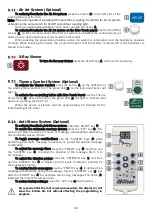
- Swivel Right Armrest (Optional)
To move the swivel armrest: press the trigger (1) and push the armrest down.
6
- Instruments Operation
- Pneumatic Handpiece Couplings
Before starting the operation connect the handpiece (1) to
the coupling by attaching it to the coupling ring (2), ensuring that
it is properly connected and that there is no leakage of air or
water.
To activate the rotation: press the propulsion/activation
pedal (5). The higher the pressure applied to the pedal, the more
speed in the handpiece, until reaching the pressure limits of the
equipment.
To adjust the spray: turn the adjusting ring (4) until the desired volume of water. To
adjust the maximum flow of water, bring the spray adjustment indicators (3) closer to each
other. To decrease the flow of water, rotate the ring so it distances one indicator from the other. The completely
opposite points indicate the minimum water regulation for the spray.
- Optical Fiber Handpiece (Optional)
Before starting the operation connect the optical fiber
handpiece to the coupling by attaching it to the coupling
ring (1), ensuring that it is properly connected and there is
no leakage of air or water.
To
activate
the
rotation:
press
the
propulsion/activation pedal (2). The higher the pressure
applied to the pedal, the more speed in the handpiece, until
reaching the pressure limits of the equipment.
To turn the coupling’s light On/Off:
use the On/Off
optical fiber light (3) on the command panel (
section 5.4
) or
the On/Off key (4) on the left side of the working table (
section 5.4
).
To adjust the spray: use the optical fiber water control knob (5) on the
instruments control panel.
- Electrical Micromotor (Optional)
Before starting the operation, connect the handpiece to
the electrical micromotor (2).
To activate the rotation: press the progressive/activation
pedal (1).
6.3.1
- Electrical Micromotor Basic Adjustments
To adjust the speed: turn the control knob (3) until the desired speed
is reached.
To change the rotation direction: use the rotation direction control (4).
FWD: clockwise;
OFF: Off;
REV: counterclockwise.
Summary of Contents for Flex Quality
Page 1: ......
Page 2: ......
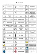
Page 20: ...20 7 Symbology The symbology complies with IEC 60601 1 and IEC 60878...
Page 27: ...27...
Page 29: ......
Page 30: ......
Page 48: ...20 7 Simbolog a S mbolos en conformidad con las normas IEC 60601 1 y IEC 60878...
Page 55: ...27...


