


XIII. Toner supply
1. Turn ON the Main Power Switch and then Sub
Power Switch.
2. Display the Service Mode screen.
(For details of how to display the Service Mode
screen, see the service manual.)
3. Touch “Imaging Process Adjustment.”
4. Touch “TCR Toner Supply.”
5. Touch "Cyan", "Magenta", "Yellow", and "Black",
and press the start key.
* When the start key lights up blue, go to step 6.
6. Touch “OK.”
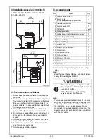
XIV. Non-image area erase check
1. Select the Non-Image Area Erase Check function
as follows:
Machine
→
→
Non-Image Area Erase Check.
Note:
• Open fully the original cover / reverse automatic
document feeder.
(When OC-509/DF-617 are installed previ-
ously.)
• Do NOT place a document on the document
glass.
• Clean the document glass if dirty.
2. Press the Start key.
3. Make sure that “Result” is “OK.”
Note:
If “Result” is “NG1” or “NG2”, review the place and
direction of installation, or take measures to block
the light source (by covering it, etc.), then perform
installation checking again.
(If a fluorescent light or other bright light sources
exist right above the machine, the light source can
hinder installation checking and cause operation
errors in the Non-Image Area Erase Check. For
detailed information, see the service manual.)
4. Touch “OK.”
5. Touch “Exit” on the Service Mode screen.
6. Turn OFF and ON the Main Power Switch.
Note:
When displayed the Service Mode screen, be sure
to turn off the main power after exiting the Service
Mode screen and wait for 10 seconds or more
before turning on.
XV. Adjusting touch panel
1. Press the accessibility key.
2. Touch “Touch Panel Adjustment.”
3. Using the panel pen, lightly touch the center of
the + markers at four places on the touch panel.
(Any specific marker can be the first one.)
Note:
Pressing the touch panel hard may cause dam-
age.
* When all the markers at four places have been
touched, the start key turns blue and lights up
steadily blue.
4. Press the start key.
5. Touch “Close.”
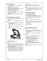
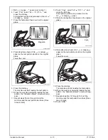
XVI. Setting gradation adjust.
Note:
Before starting the gradation adjustment, install
the optional reverse automatic document feeder or
the original cover.
1. Set that A3
or Ledger
paper is loaded in
the tray.
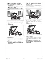
Note:
If the A3
or Ledger
paper is not readily
available, use A4
or Letter
paper.
2. Display the Service Mode screen.
(For details of how to display the Service Mode
screen, see the service manual.)
3. Touch “Imaging Process Adjustment.”
4. Touch “Gradation Adjust.”
5. Touch “Stabilizer” and press the start key.
* When the start key lights up blue, go to step 6.
Note:
When a maintenance call occurs, see the service
manual.
A0P0IXC091DA
Y111050-6
E-
9
Installation Manual


