background image

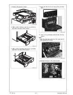
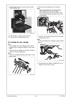
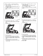
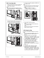
13. Slightly slide the drum unit (K) out and remove 

the protective tape.

14. Slide the drum unit (K) into the machine.
15. Lock the drum unit (K) with the lever.

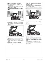
VII. Installing the toner cartridge

Note:

Since cartridge is not furnished with the machine, 
purchase toner cartridge (of different colors) sepa-
rately.

1. Shake the toner cartridge up and down and left to 

right 5 to 10 times respectively.

Note:

Shake the cartridge adequately. Otherwise, it may 
cause trouble.

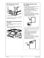
2. Insert the toner cartridge into the machine.

Note:

    • Make sure that the color is same between 

inserting port and the toner cartridge.

    • Make sure that the blue label position of the 

toner cartridge is matched with the one of the 
machine side.

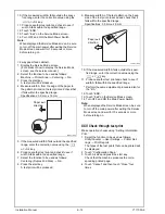
3. Push the toner cartridge all the way in and rotate 

it clockwise to lock it.

Note:

Make sure that the toner cartridge is pushed all the 
way in.

4. Using the same procedure, install the toner car-

tridges for other colors of toner.

A0EDIXC019DA

A0EDIXC020DA

A0EDIXC021DA

A0EDIXC022DA

Installation Manual                                                          E-

6


Y111050-6

Summary of Contents for d-Color MF280

Page 1: ...al cover be sure to install the hinge covers furnished with the original cover Once the Power Switch is turned ON do not turn OFF it until the installation work has been completed Lifting the machine...

Page 2: ...essary for mounting the FAX Kit Note This manual provides the illustrations of the acces sory parts and machine that may be slightly differ ent in shape from yours In that case instead of the illustra...

Page 3: ...appropriate size for transporting the machine When attaching the machine as the reference fit the machine with the corner A and B of the paper feed cabinet VI Removing protective tape packing and othe...

Page 4: ...roller assy into place so that it is secured as shown in OK 3 Remove the packing bracket 4 Install the furnished control panel Note Insert the hook of the control panel into the posi tioning hole of t...

Page 5: ...om the inside of the drawer 10 Open the front door and remove the protective tape 11 Remove the protective materials from the four places Note Keep the protective materials It is necessary for transpo...

Page 6: ...artridge adequately Otherwise it may cause trouble 2 Insert the toner cartridge into the machine Note Make sure that the color is same between inserting port and the toner cartridge Make sure that the...

Page 7: ...oor IX Mounting the accessory parts 1 Attach the cap A and B furnished with the machine 2 Set the panel pen in the pen holder at the control panel X Installing the user s guide holder spacer Install t...

Page 8: ...l bypass tray and set the set guide for banner paper XII Connecting the power cord 1 Remove the screw at the rear of the machine 2 Connect the power cord 3 Fit the cord clamp furnished with the machin...

Page 9: ...e service manual 4 Touch OK 5 Touch Exit on the Service Mode screen 6 Turn OFF and ON the Main Power Switch Note When displayed the Service Mode screen be sure to turn off the main power after exiting...

Page 10: ...machine read the test pattern two times three times in total 12 Touch Copy select A3 11 17 and press the start key A test pattern will then be produced on the A3 or Ledger paper 13 Place the test patt...

Page 11: ...machine read the test pattern two times three times in total 12 Touch Copy select A4 8 11 and press the start key A test pattern will then be produced on the two A4 or Letter papers 13 Place the test...

Page 12: ...g the Entry key returns the figures in the Install Date screen to 0 and Install Date has been completed 6 Touch END XIX Serial number input Note Serial number input is needed only for optional devices...

Page 13: ...the start key A test print will be produced 4 Measure width A from the edge of the paper to the pattern printed on the test print and check that it falls within the specified range Specifications 3 0...

Page 14: ...used as follows Centering Duplex 2nd Side 3rd 8 Press the start key A test print will be produced 9 Measure width A of the test pattern on the back side of the test print produced and check that it fa...

Page 15: ...ss setting for the network Note Consult the network administrator for the setting value to be entered and make settings as required 1 Select the function to be used as follows Utility Counter Administ...

Reviews: