
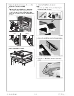
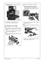
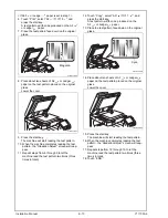

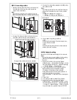
VIII. Installing the waste toner box
1. Remove the protective tape from the furnished
waste toner box.
2. Install the waste toner box.
3. Close the front door.
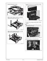
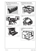
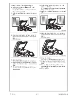
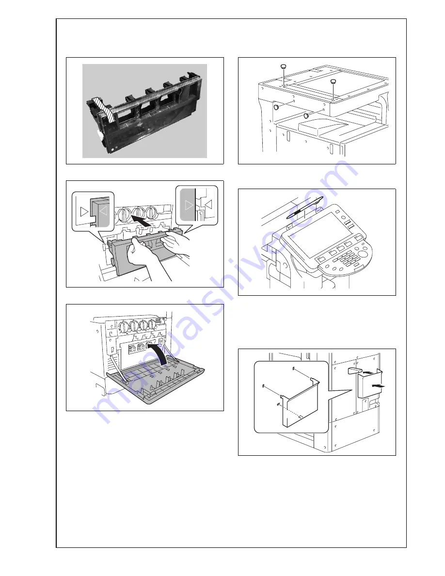
IX. Mounting the accessory parts
1. Attach the cap A and B furnished with the
machine.
2. Set the panel pen in the pen holder at the control
panel.
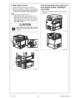
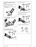
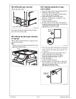
X. Installing the user’s guide holder/
spacer
Install the user’s guide holder and the spacer.
A0EDIXC024DA
A0EDIXC025DA
A0EDIXC023DA
A0EDIXC026DA
A0P0IXC055DA
A0EDIXC027DA
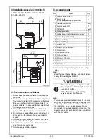
Y111050-6
E-
7
Installation Manual


