Oliver M1013 Owner'S Manual Download Page 21


21 

Setting Up To Carve (cont.) 

Using the control panel 


1

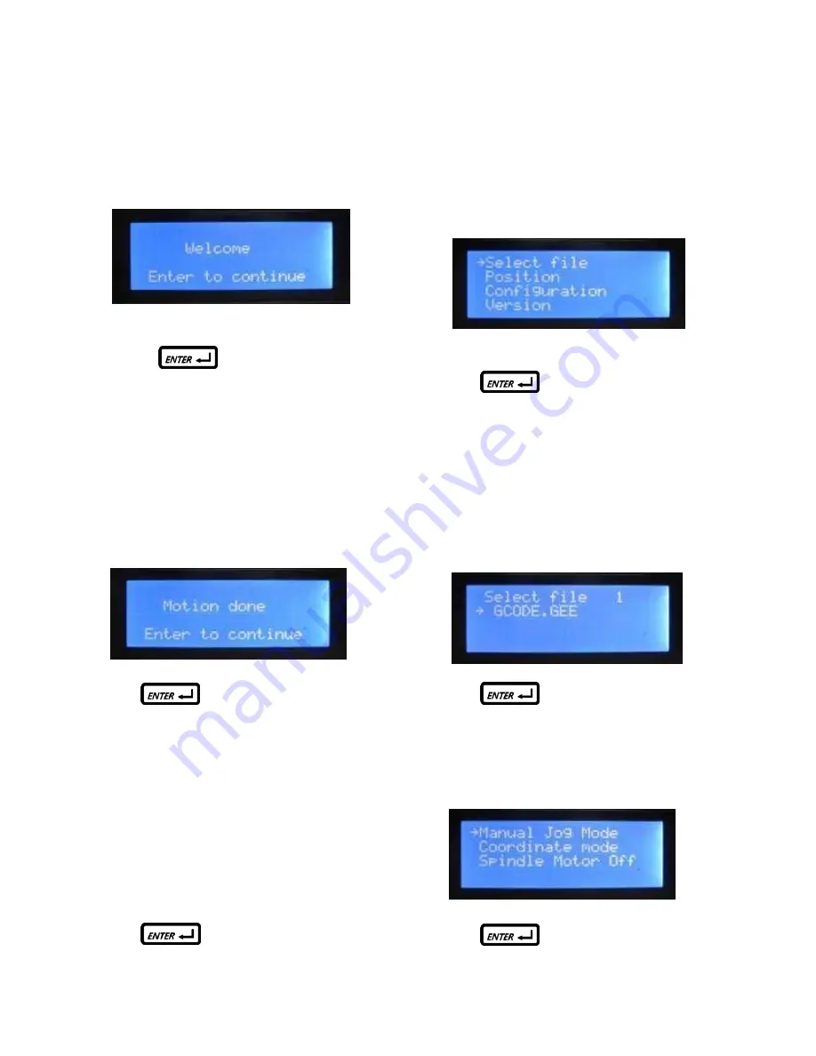
. When you first turn the machine on you will notice 

the control panel display will read: 


Pressing 

on the keypad will automati-

cally start the spindle toward its home point (X=0, 

Y=0, Z=0).                                                                                                                                                                                                                                                 


2

. After the spindle reaches its home point, the dis-

play will read: 


Press 

to continue. 


3

. The next three screens will prompt you to check: 

a. Is the ‘cutting tool’ is secure? 

b. Is the ‘workpiece’ secure? 

c. Is the flash drive in the ‘USB’ port? 


Press 

after confirming each of these. 


4

. The next screen to appear is the main operating 

screen as seen below.    Use the arrow button on the 

con

troller to set the cursor to ‘Select file’ as shown: 


Press 

to continue. 


5

. Use the arrow buttons to scroll up or down to the 

desired file as indicated by the cursor (this is the file 

you converted from i-Picture and copied to the flash 

drive)

.    In this case the file is called ‘GCODE.GEE’ 

as shown: 


Press 

to continue. 


6

. Select ‘Manual Jog Mode’ as show: 


Press 

to continue. 

Summary of Contents for M1013

Page 1: ...1 1013 intelliCarve Owner s Manual Oliver Machinery M 1013 7 2011 Seattle WA Copyright 2003 info olivermachinery net www olivermachinery net...

Page 2: ...use negligence accidents unauthorized repairs alterations lack of maintenance acts of nature or items that would normally be consumed or require replacement due to normal wear In no event shall Oliver...

Page 3: ...atically 6 Avoid the risk of danger not play or run in the work area 7 Do not touch the spindle or cutting tools with bare hands before the machine is completely stopped 8 Pay attention to the warning...

Page 4: ...all The Cutting Tool 12 Cutting Tools 13 14 Conical Bit 13 End Mill Bit 14 Installing i Picture Software 15 Using i Picture 15 18 Getting Ready To Carve 19 23 Powering Up 19 Setting the Work Piece On...

Page 5: ...elliCarve users only need plug the USB into the intelliCarve then select a file for carving and push a few buttons to complete the carving Knowledge of CAD CAM software is not necessary 2 Light i Pict...

Page 6: ...rving speed Metric Imperial system available Supports manual carving without program Maximum engraving area simulation Supports file category tree structure Spindle and stepper motors overload protect...

Page 7: ...rushless 4 Transmission 4 1 X Z lead screw diameter 16mm 0 63 4 2 X Z rail material IGUS WX 01 10 4 3 Y axis Rack pinion 6 Feed Speed 6 1 speed 3M min 118in min 6 2 position accuracy 0 1mm 0 004 6 2 r...

Page 8: ...8 Specifications cont 10 Dimension Weight 10 2 Space WxL 630x560x530mm 25 8x22 0x20 8 10 3 weight 28 Kg 61 6lbs 11 Others 11 1 power in AC 110V 6A 50 60Hz 11 3 software i Picture for intelliCarve...

Page 9: ...een damaged please report the damage to the freight carrier Standard Packaging 1 Tool Box 2 USB flash drive I picture software 3D sample pictures 3 collet 4 Collet nut 5 Conical bit 0 8mm Radius 6 End...

Page 10: ...ntelliCarve The Components see Fig 2 3 1 Spindle motor 7 Emergency stop 2 Spindle lock 8 Power switch 3 Table 9 USB port 4 Work piece hold downs 10 Lift handle left 5 Lift handle right 6 LCD display a...

Page 11: ...ng to the operator s position facing the front spindle Directional Conventions 1 X spindle head moves right 2 X spindle head moves left 3 Z spindle head moves up 4 Z spindle head moves down 5 Y table...

Page 12: ...order to engage the lock 3 Loosen the nut with an open end wrench turning clockwise 4 Release the bit 5 To install a new bit place the collet into the nut Then put the bit into the nut and collet Scre...

Page 13: ...t Tool Model No 381044 000 Material Carbide Flute 2 Flute length 1 Cut depth Max 1 Shank diameter Overall length 2 36 Cutting edge radius 0 8mm Various types of woods Recommended max depth of cut per...

Page 14: ...l Bit Tool model No 381020 000 Material Carbide Flute 2 Flute length 0 47 Cut depth Max 0 45 Shank diameter End mill diameter 3 175mm Overall length 2 36 Various types of woods Max depth of cut per cy...

Page 15: ...ox and insert it into the USB port of your personal computer Locate the executable file labeled i Picture_v1 2 exe and click to begin in stallation Follow the prompts to complete the installation Usin...

Page 16: ...lithophanes Scan step is the distance the Y axis moves on every carving along the X axis The lower number the Scan step is the more detailed your image will be but the longer it will take to produce D...

Page 17: ...iscussed later in section 7 If using a single piece of material for one carving it may be advantageous to start in the center as this is an easy point to find on your material However if carving sever...

Page 18: ...w minutes please Wait and in a few moments you will see a blue progress bar begin When finished the following screen will appear prompting you to save the file Here you can change the File name and sa...

Page 19: ...ve Ensure carving bit is secure in machine before proceeding 1 Insert the flash drive into the USB slot see picture A 2 Rotate emergency stop button clockwise to release see picture B 3 Turn rocker sw...

Page 20: ...osition on the work table Two hold downs are supplied with the machine to accomplish this First place the work piece against the fence D as shown in the picture below Slide the hold down A up to the w...

Page 21: ...utting tool is secure b Is the workpiece secure c Is the flash drive in the USB port Press after confirming each of these 4 The next screen to appear is the main operating screen as seen below Use the...

Page 22: ...the Y dimension of your carving is between the minimum and maximum of the ruler on the fence Use the X Y and Z plus and minus keys to move the spindle to the center of your work piece Note that for th...

Page 23: ...outside border of your carving move the cursor to Border and press This is helpful if there is concern of the spindle bumping into something If you wish to continue move the cursor to Process and pre...

Page 24: ...g with lithophanes keep in mind that your end product will be a mirror image of your pho tograph You may wish to reverse your photograph before uploading it to i Picture This can be done with photo ed...

Page 25: ...y intricate work where fitting with another part is required may be a problem Oliver Machinery is not responsible for work done using after market CAD CAM software Origin repeat If you wish to run the...

Page 26: ...ess Step 2 Select coordinate mode and press Step 3 Select X and press Step 4 Cursor turns to block flash for adjustment status Step 5 Press up or down key to input coordinate reading for this example...

Page 27: ...ess Step 2 Select Spindle Motor Off then press Cursor turns to block flash for adjustment status Step 3 Press up or down key to change status for this example press down key to turn on spindle motor C...

Page 28: ...Press and cursor turns to block flash which means it is ready to edit Press the up or down key to change the setting from mm to inches Step 5 Press Down key on keypad to change to Imperial unit Unit...

Page 29: ...it will set the 3 ax es to their home coordi nates automatically Go to e if this does not work e Ensure the 3 axes are in their correct positions If not see X Y Z compo nents f The axes do not stay in...

Page 30: ...ol Panel wire is connected Connect the wire Contact your local dealer or distributor if this does not help 6 Choose Select File on the Control Panel and the front LEDs light red Ensure USB Flash drive...

Page 31: ...or wire is loose Ensure terminal pin is tight Secure the cover back to the place Then turn on the power switch Select Enter to carve Contact your local dealer or distributor if this does not help 2 Ab...

Page 32: ...t breaks 1 Cutting depth is over loaded 2 The hardness of the material is too high 3 Bit becomes dull Restart carving your workpiece 4 The outcome does not match your computer file Ensure you install...

Page 33: ...909 Z Axis Positioning Plate 6463 1 FH010102 7 922494 000 Block WJ200UM 01 10 8 8 000103 102 CAP Screw M6 1 0P 10 46 HA020404 9 006501 100 Serrate Washer 4 3 8 5 BW 4 7 HE040600 10 000302 702 Hex Hea...

Page 34: ...i 4 FH010055 37 310266 909 Bracket 6463 2 FH010098 38 002602 101 CAP Lock Screw M6 1 0P 12 8 39 008913 100 Nut MR12 1 0P 2 40 000102 106 CAP Screw M5 0 8P 20 24 HA020310 41 006302 100 Spring Washer 5...

Page 35: ...12 72 490785 000 Fan DC 24V 2 04W 1 490779 000 73 250895 615 Fan Cover ABS 1 74 001201 909 Point Cutting Self Tapping Screw M4 1 59P 25 4 75 250144 615 Winder Base 2 PH010023 76 001203 902 Point Cutti...

Page 36: ...nd Head Screw M6 1 0P 16 1 HA040708 103 130277 000 Gear 1 FH010095 104 001904 104 SET Lock Screw M4 0 7P 8 2 105 310258 909 Y Axis Motor Bracket 6463 1 FH010088 106 173236 000 Plate 1 107 000104 708 C...

Page 37: ......

Reviews: