


ENGLISH
EN - 2
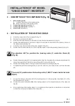
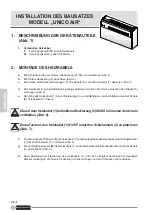
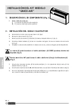
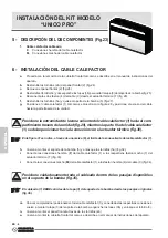
INSTALLATION OF KIT MODEL
“UNICO AIR”
1 - DESCRIPTION OF THE COMPONENTS (Fig.1)
1.
Wired heating cable
F.
Female connections of the heating cable
M.
Male connections of the heating cable
2 - INSTALLATION OF THE HEATING CABLE
a.
Undo the screws (2a) of the rear panel (2) (fig.2).
b.
Remove the rear panel (2) (fig.2).
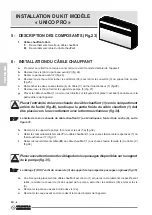
c.
Disconnect the two faston (3) of the cable (C) from the thermal-actuator (T) (fig.3).
d.
Position the heating cable (1) as shown in figure 4. Force its curvature between the veining (5) (fig.5).
e.
Complete the path of the heating cable (1) up to the mark (6), then make it come out from the basin
(B).
The mark (6) positioned on the heating cable (1) MUST remain inside the basin
(fig.6).
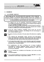
Pay attention NOT to position the heating cable (1) under the floats (4)
(Fig.7).
f.
Connect the female connections (
F
) of the heating cable (1) to the respective male faston (7) of the
thermal-actuator (T) (fig.8).
g.
Connect the male connections (
M
) of the heating cable (1) to the female faston (3) of the cable (C)
(fig.9).
h.
Once positioning of the heating cable (1) is complete and the respective connections are connected,
remount the rear panel and tighten the screws (2a).
Summary of Contents for KIT B0620
Page 2: ......
Page 3: ...1 F M 2a 2 2 1 2 UNICO AIR...
Page 4: ...1 T 3 C 1 5 5 1 6 B 3 5 6 4 UNICO AIR...
Page 5: ...7 F 1 T 1 1 NO OK 4 4 3 C M 1 8 7 9 UNICO AIR...
Page 6: ...5a 5 5 1 3 4 F M 2 10 11 UNICO SMART INVERTER...
Page 7: ...T 6 C 7 7a 3 3 4 4 12 14 15 13 1 2 UNICO SMART INVERTER...
Page 8: ...7 7a 3 4 1 7a 18 7 7 3 4 4 17b 17a 1 1 8 8 NO OK 16 UNICO SMART INVERTER...
Page 9: ...9 9 1 1 B 10 20 19 11 T F 1 6 M C 1 21 22 UNICO SMART INVERTER...
Page 10: ...1 F M 2a 2 23 24 UNICO PRO...
Page 11: ...3b 3a 3 5a 5 5a 5a T 4 C 25 27 26 UNICO PRO...
Page 12: ...1 30 1 28 1 29 UNICO PRO...
Page 13: ...T 7 F 1 33 Z3 6 1 31 5a 5 5a 5a 32 UNICO PRO...
Page 14: ...1 3 C M 1 34 3 1 3b 3a 3b 1 36 UNICO PRO 35...
Page 43: ......
Page 44: ...277276C...