background image

English

65

8.2  

Overview


„

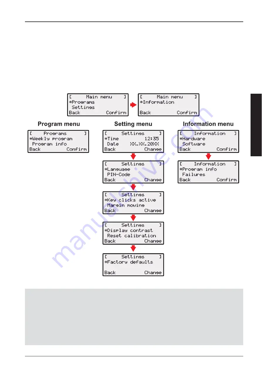
The main menu of the robot lawnmower is divided up into the following submenus: 


„

Program menu.


„

Setting menu.


„

Information menu.

Note!


„

Start the robot lawnmower as described.


„

Use the [up arrow key] or the [down arrow key] to select the required main menu.


„

The star symbol to the left of the menu displays shows which selection is active.


„

Confi rm the required main menu with the [multifunction key right]. The corresponding sub-menus open. 


„

Confi rm the required application with the [multifunction key right]. Change the sub-menu items if required.


„

Use the [multifunction key left] to return to the standard display.

Summary of Contents for orion 700

Page 1: ...ORION 700 I MANUALE USO E MANUTENZIONE GB OPERATOR S INSTRUCTION BOOK...

Page 2: ......

Page 3: ...Italiano ISTRUZIONI ORIGINALI 5 English TRANSLATION OF ORIGINAL INSTRUCTIONS 43...

Page 4: ......

Page 5: ...the language see page 68 Enter PIN code see page 59 Changing the PIN code see page 59 Activate or deactivate the button tones see page 68 Changing the display contrast on the LCD display see page 69...

Page 6: ...ere is any transport damage immediately notify your dealer If the robot lawnmower was sent by a parcel service retain the original packaging and accompanying documents 1 2 Scope of supply Item Name It...

Page 7: ...on of function 50 4 3 Control panel 51 4 4 Sensors in the robot lawnmower 51 4 5 Base station 52 4 6 Transformer 52 4 7 Boundary cable 52 5 Assembly installation 53 5 1 Assembling the base station 53...

Page 8: ...ng the cutting height 62 7 3 Charging the battery in the robot lawnmower 62 7 4 Exhaustively discharged battery 63 8 Programming 64 8 1 Starting the robot lawnmower 64 8 2 Overview 65 9 Program menu 6...

Page 9: ...move freely 71 14 2 Checking cleaning contacts 71 14 3 Checking cleaning the base station 72 14 4 Cleaning the chassis 72 15 Repair 72 15 1 Renewing the cutting blade plate 72 16 Technical data 73 17...

Page 10: ...The robot lawnmower must never be used to transport push or tow trailers or other similar objects 5 It is prohibited to fit implements or accessories other than those supplied by the manufacturer 3 Sa...

Page 11: ...ions for use During mowing make sure that no one places any part of their body in the vicinity of the rotating cutting blades If the robot lawnmower is defective e g on its cutting blade s cable or ba...

Page 12: ...attery operated lawnmower which moves freely within a defined mowing area The mowing area is defined by a boundary cable that is connected to the base station In order for its battery to be recharged...

Page 13: ...bot will restart automatically after approximately 2 minutes Use the multifunction keys right or left 7 or 8 to confirm or revoke commands for example selecting a menu command The ON OFF key 9 is used...

Page 14: ...erates a control signal and sends this in the boundary cable 3 There are two charging contacts 2 on the base station 4 which contact the charging contacts on the robot lawnmower as soon as it moves in...

Page 15: ...on smooth level ground where it will be protected against the rain Then use lawn pegs to secure it in place white dots Comply with the specified dimensions when doing this Remove the insulation from t...

Page 16: ...has been laid on the grass do not scarify the area of the boundary cable any longer Laying options max 5 7 cm 1 2 The boundary cable can be laid on the lawn 1 and as much as 5 7 cm under the turf 2 Ha...

Page 17: ...the minimum distances from obstacles and the minimum passage width otherwise the robot lawnmower will not be able to operate correctly STOP If there is a crossover in the boundary cable layout this wi...

Page 18: ...in 30 cm 0 cm 5 6 Connecting the boundary cable to the base station 1 2 Remove the insulation from the boundary cable 2 after laying the cable and connect to the spring terminals 1 5 7 Connecting the...

Page 19: ...ight up when the cables are connected If this is not the case pull out the mains plug and check if all plug connections and cables are correctly seated also check them for damage The yellow LED 1 ligh...

Page 20: ...mower by pressing the ON OFF key The LCD display then shows the illustrated information Display after the status display The LCD display shows the information Uncalibrated The LCD display automaticall...

Page 21: ...Change PIN dialog box 6 5 Changing the PIN code 1 Enter a new PIN and repeat 2 Confirm the last entry with multifunction key 3 After this the LCD display shows the Date dialog box 6 6 Setting changing...

Page 22: ...e automatic calibration procedure starts when the START key is pressed The Drive starting warning flashes on the LCD display Calibration procedure starts The robot lawnmower first moves straight over...

Page 23: ...ase station 3 In case of collisions or if the boundary cable is laid too close the robot lawnmower will cancel its movement 4 Rectify the error place the robot lawnmower about 1 m in front of the boun...

Page 24: ...ed Pull lever 2 upwards Lawn cutting height is increased Push lever 2 downwards Lawn cutting height is reduced After cutting height adjustment Turn lever 2 a quarter turn anticlockwise in the directio...

Page 25: ...wnmower into storage for the winter please make sure it is fully charged After 3 months of storage check the battery status switch on the robot lawnmower and read the battery charge level If necessary...

Page 26: ...ven regarding the next mowing Note The displayed mowing operation may be the factory setting unless a new mowing operation has already been programmed Note The PIN code may also be the factory code if...

Page 27: ...key or the down arrow key to select the required main menu The star symbol to the left of the menu displays shows which selection is active Confirm the required main menu with the multifunction key r...

Page 28: ...t and confirm with the multifunction key right in each case Mowing time setting in batch mode 1 Select the required menu item Every day with the arrow keys and confirm with the multifunction key right...

Page 29: ...amming depends on the time Confirm individual digits and use the arrow keys to select the next digit The time is displayed in 24 hour format 1 Select the required time with the arrow keys and confirm...

Page 30: ...play or press the arrow key 2 once briefly A 9 flashes at the first place in the display 2 Either use the down arrow key to count down from 9 or use the arrow key to count up until the required digit...

Page 31: ...tance covered Software status with version number Note The Information menu is used for calling up various information such as software status hardware status and current settings No settings can be m...

Page 32: ...l set number of mowing hours is displayed Times per programming the day of the week and the time when mowing takes place The total set mowing time in the week is displayed 13 Transport 1 2 When transp...

Page 33: ...robot mower to the workshop after 500 and 2500 hours operation for General check on tightness of bolts and mechanical parts Check on error statistics Check on battery status Check on wheel bearings I...

Page 34: ...f the robot lawnmower at the ON OFF key before starting maintenance and repair work Always wear working gloves when carrying out maintenance and care jobs on the blade system Disconnect the transforme...

Page 35: ...ngth in mm 600 Width in mm 490 Height in mm 245 Weight in kg approx 8 Mowing system Electric with 2 cutting blades Cutting blade motor rpm 3400 Cutting heights in mm 30 60 Cutting height adjustment 5...

Page 36: ...ed by an electronic control unit which displays malfunctions and the status on the LCD display of the robot lawnmower 6 5 4 1 2 3 1 Time 4 Fault code 2 Fault message 5 Date 3 Actuation panel 6 Malfunc...

Page 37: ...PIN code Three attempts are possible after which a PUK code must be entered Uneven mowing result Working time of the robot lawnmower is too short Program longer working times Mowing area too large Pr...

Page 38: ...ng of the boundary cable curves obstacles etc CN012 Cal no loop CN015 Cal outside Error during calibration the robot has not detected the circuit Position the robot at right angles with respect to the...

Page 39: ...he problem recurs have the robot checked by an authorized service centre CN119 R Bumper deflected CN120 L Bumper deflected The robot has collided with an obstacle and is unable to break free for reaso...

Page 40: ...make any claim under the warranty this certificate of warranty fully completed bearing the dealer s stamp and accompanied by the invoice or receipt showing the date of purchase must be displayed to th...

Page 41: ...nd of their life Dispose of in accordance with local regulations In accordance with Directives 2002 95 CE 2002 96 CE and 2003 108 CE on the reduction of hazardous substances in electrical and electron...

Page 42: ...ina durante tutta la sua vita GB WARNING This owner s manual must stay with the machine for all its life It s an EMAK S p A trademark 42011 Bagnolo in Piano RE Italy Tel 39 0522 956611 Fax 39 0522 951...

Reviews: