


MG-IP TDM Over IP Gateway Reference Manual
34
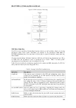
Underrun Ethernet packets: the jitter buffer underrun condition occurs when there is no
correctly received ToP payload ready to be played out on the TDM interface, and filler
packets are played out instead. This may occur due to frames getting lost on the Ethernet
network, or discarded due to error conditions.
Overrun Ethernet packets: the jitter buffer overrun condition occurs when the jitter buffer
cannot accommodate the newly arrived packet in its entirely (e.g. due to insufficient storage
space).
Invalid Sequence Ethernet Packets: packets with sequence numbers completely outside the
expected range. These packets are automatically discarded.
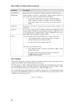
End-To-End Delay Calculation
The end-to-end delay of a CES frame can be calculated as follows:
End-to-End delay = (Packetization Delay + Tx Processing Delay) + Constant Network Delay +
(Maximum Jitter Buffer Delay + Rx Processing Delay)
Packetization Delay - 0.125 milisecond * number of frames configured (payload size)
Tx Processing Delay - depends on the configuration and will always be shorter than 1 ms.
Constant Network Delay - Constant delay of the network. Varying delay (or delay variation)
will be absorbed by the jitter buffer.
Maximum Jitter Buffer Delay - The size of the preset maximum jitter buffer
Rx Processing Delay - depends on the configuration and will always be shorter than 1 ms.
Bandwidth per Pseudowire
The amount of bandwidth required by a pseudowire drops as a function of the number of frames
encapsulated in each packet. More frames per packet payload means fewer packets per second, and
therefore fewer packet headers.
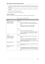
Table 3 lists sample network bandwidth requirements for different packet payload sizes when the data
is unstructured.
Table 3: Bandwidth Requirements (SATOP Header)
Line Format No. of Frames Per Packet Packets/Sec. Bandwidth Required (Mbps)
2 4000
4.032
4 2000
3.040
8 1000
2.544
16 500
2.296
E1
32 250
2.172
2 4000
3.538
4 2000
2.541
8 1000
2.042
16 500
1.793
T1
32 250
1.668