


Construction Manual
www.oldschoolmodels.com
Page 9
Step 60 - Fuselage Assembly (pushrod tubes)
This step is optional, but
is easier to do now, before
the bottom sheeting is
applied.
Depending on the type
of pushrods you intend
to us with the Wayfarer
(not included), we would
suggest installing them
now.
In the prototype
shown here, we
used Dubro’s
flexible Lazer
pushrods. We
chose to install the
outer sleeves in
place now and you’ll see that there are cutouts in F4, F5, F6 and
the fuselage sides to accomodate most any type of pushrods.
Step 61 - Fuselage Assembly (FS4)
Locate FS4 from LP3. This is the
bottom fuselage sheeting. Glue
the front edge in first, then work
your way backwards, gluing a
little bit at a time.
Step 62 - Fuselage Assembly (bottom sheeting)
Now using the rest of the
1/16” sheet, measure
cut and glue the bottom
sheeting to the fuselage.
Start at the rear of the FS4
sheeting and work your
way towards the back of
the fuselage. Remember,
cross-grain for strength.
Step 63 - Fuselage Assembly (FS1)
Locate FS1 from LP3. This is
glued in place on top of the
fuselage, on top of F1, as
shown.
Step 64 - Fuselage Assembly (top hatch)
Locate FS2 and FS3
from LP3. FS3 is
the top hatch and
FS2 is glued to
FS3 as shown in
this diagram. Note that
there is a line etched into FS2 to aid in aligning the two pieces
when gluing.
Step 65 - Fuselage Assembly (thumb screw)
When the hatch is completed,
place in position on top of the
fuselage. Make sure it is lined up
with the fuselage side and the
front hold-down (FS2) of the top
hatch is slid all the way under FS1.
You may need to sand FS2 slighly
to aid in it sliding in.
When satisfied with the fit, transfer
the hole in the hatch to FS9, by tracing around it with a pencil.
Drill and tap FS9 for a 10x32 thread. A 5/32” drill will work to
create the hole and if you don’t have a 10x32 tap, you can use a
like 10x32 bolt (made of metal) to cut the threads.
When finished, you should have a hole where the included 10x32
thumb screw can be used to hold the front hatch in place.
Step 66 - Fuselage Assembly (vertical fin support)
Now carefully cut the vertical
fin’s support at the back of the
fuselage as shown here. This will
allow the stab to be installed in
the next step.
Step 67 - Fuselage Assembly (stab install)
Slide the horizontal stab into
the fuselage. Before gluing
in position, make sure that it
is perpendicular (90°) to the
vertical fin. Use the included
triangle to aid in alignment.
When gluing in position,
make sure it is centered. Take
measurements from the each
tip of the stab to the side of
the fuselage. Adjust as necessary to make these measurements
are the same. Also measure from each tip to the center of the
fuselage’s nose. These two measurements should also be equal.
Once satisfied with the alignment, glue the stab to the fuselage.
Step 68 - Wing Assembly (sanding)
Work now shifts back to the wing panels. Take some time to sand
the entire wing. Take the time to round the leading edges to an
airfoil shape, as well as shape the tips so they are both aerodynamic
and match each other.
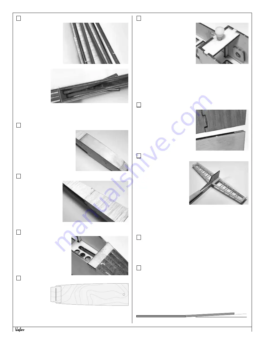
Step 69 - Wing Assembly (dihedral rod)
Included in the Wayfarer is a 10” length of 3/16” steel rod. This will
be used to create the rod to support the wing panels.
Make a mark on the center of the rod. Now you will make a sharp
bend at this center point. It’s easiest to do this by chucking the rod
in a vice, with the center point right at the top of the vice’s jaws. A
good hit or two close to the bend point with the hammer should
be enough to form the 3° needed. Use the diagram on the plans
as your guide to make the perfect bend.
Wing Joiner
- 3/16” music wire
Make a sharp 3° bend at the center.
3°


