


Construction Manual
www.oldschoolmodels.com
Page 5
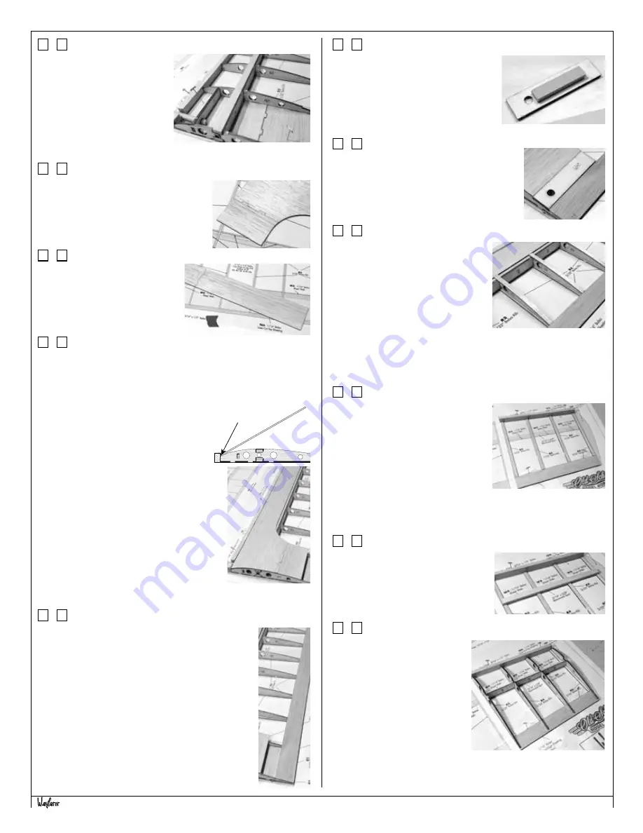
Step 15 - Wing Assembly (top spar)
Locate another of the 3/16” x
3/8” basswood strips to use as
the upper spar. Measure, cut
and glue into position as shown.
Make sure the spar is pushed
all the way into each of the rib’s
slots, and is glued to each of
the ribs and sheer webs.
Step 16 - Wing Assembly (TS1 & TS2)
Locate one of the TS1’s from BP6 and a
TS2 from BP5. These are glued together
as shown here.
Step 17 - Wing Assembly (TS3)
Locate one of the TS3’s from BP6.
This is glued to the end of the TS1/
TS2 assembly from the previous
step, as shown here.
Step 18 - Wing Assembly (top sheeting)
Now the top sheeting assembly you’ve just glued together is
attached to the wing.
It’s best to do this a little at a time, starting with the leading edge.
It’s also a good idea to have a long straight-edge (such as a metal
yardstick) to aid in holding the sheeting.
Run a bead of glue along the front
edge of the wing sheeting. Then place
the sheeting in position, making sure it
aligns with R1 and it is pressed against
the entirety of the leading edge. Pressing
that yardstick on top of the wood makes it
easier to hold long lengths of wood in place
with just two hands.
After the glue has cured, run beads of glue
along the tops of each rib, from the leading
edge, back to the upper spar. Roll the
leading edge sheeting onto this area and
press down, again with the yardstick.
Once cured, then glue the last section of the
sheeting to R1 and R2.
Step 19 - Wing Assembly (trailing edge sheeting)
Locate two more lengths of the laser-cut 1” strips
that are cut into several of the 1/16” sheets (BP5,
BP6, and BP7). These two pieces will need to be
joined together to make a long enough strip to form
the upper trailing edge. Measure and trim to length,
then pin and glue into position. Again, the joint
should be on an angle, not a 90° butt-joint.
Step 20 - Wing Assembly (WH1)
Locate WH1 from LP1. Also cut a 3/4”
piece from the leftover 3/16” x 3/8”
basswood used in the spars. Glue this
as shown here, centered on WH1 and
up against the hole. This will act as a
support in the next step.
Step 21 - Wing Assembly (WH1)
Glue WH1 into the gap between the leading
and trailing edge sheeting. The hole will be
positioned towards R1.
Step 22 - Wing Assembly (cap strips)
Locate a couple lengths of the laser-
cut 1/4” cap strips that are cut into
several of the 1/16” sheets (BP5, BP6,
and BP7). These are used to make
the upper cap strips. These strips run
from the trailing edge, to the rear of
the leading edge sheeting. Measure,
cut, pin and glue these into position
as shown.
Note that the cap strip on top of R3 should be positioned so it is
flush with outer edge of the rib, not overlapping it.
Step 23 - Wing Assembly (outer wing)
The outer panels are made the same
way as the inner wing you just built -
just smaller.
Locate a length of the laser-cut 1”
strip for the trailing edge and the
laser-cut 1/4” cap strips that are cut
into several of the 1/16” sheets.
Also cut a portion of the leading edge
5/16” x 1/2” strip. Measure, cut, pin and glue these into position
as shown here.
Step 24 - Wing Assembly (outer wing)
Cut a piece of the leftover 3/16” x
3/8” basswood strips to use as the
lower spar. Measure, cut and glue into
position as shown.
Step 25 - Wing Assembly (outer ribs)
Locate R6 from BP2, also one
W6 from BP8. Note that W6
tapers from one end to the
other. Fit the shorter end into R6
and glue at a 90° angle, making
sure it’s on the correct side.
When cured, glue this in
position. Now do the same with
R5 and R4.
R3 will be glued in place, but be
sure to use the 3° angle tool that you used previously.
Glue here
first


