background image

                  Construction Manual 

www.oldschoolmodels.com 

Page 7

and WH4 from the LP4 sheet. Also, cut a 1-1/4” length from the 

included 1/4” dowel and round off one of the dowel’s ends.

These pieces all interlock together so we suggest dry fitting these 

components the first time.

In the rounded part of the WH1’s and WH2 is a 1/4” dia. hole. Slide 

the non-rounded end of the 1/4” dowel through one of the WH1’s 

and push it through so it extends a 1/4” out of the opposite side. 

Next push the WH2 on, and finally the other WH1. By lining up the 

WH1’s and the WH2, you’ll see that their tabs will now slide into the 

slots in WH3. Once WH3 is in position, the remaining tabs on WH2 

can now be slid into WH4, and then into WH5, already installed on 

the wing.

After you see how all these pieces go together, disassemble them 

and re-assemble using glue. Make sure that the WH1’s and WH2 

pieces are perfectly in line before the glue sets. Then make sure 

that WH3 fits flat against WH4, and in turn, WH4 fits flat against 

WH5 as you’re gluing them together.

Step 34 - Wing Assembly (sanding)

You’ll need to take a bit of the edges off the corners of WH3, as 

it protrudes a bit from the curvature of the wing rib R2 on each 

side. Also, do not sand down any of the WH1/WH2 assembly as 

the wood that protrudes from the bottom of the wing’s surface is 

needed for strength.

Step 35 - Wing Assembly (Optional strings)

This step is optional, but 

could make the aileron 

servo installation a bit 

easier, once the wings 

are covered. Cut two 12” 

lengths of string, one for 

the left wing, and one 

for the right. Remember 

that hole cut in the lower 

sheeting, middle section 

in step 30? Starting with the left wing panel, push the thread 

through this hole, then through the circular holes in R2, R3, and 

R4. The string will now extend from the servo bay, out through the 

bottom of the wing. Tape both ends of the string so they won’t pull 

out. Do the same for the right panel.

This completes assembly of the Robinhood 25 wing.

Now it’s time to start construction of the fuselage.

Prepare your work area

Now tape the fuselage side plan and a fresh piece of waxed paper 

on your building board. 

Step 36 - Fuselage Assembly

The fuselage sides are made by first constructing the right side, 

then building the left side on top of the right side. Because of 

this, you’ll need to pay attention to where pins are used during the 

construction of the right side, so they won’t interfere with aligning 

the left side parts.

Step 37 - Fuselage Assembly (FRS)

Construction starts with the right side of the fuselage. Locate FRS 

from sheet LP1. Pin FRS in position over the plans, but do not pin 

through the wood. Instead, 

use a few pins around the 

outside of FRS as shown in 

the photo. Mark the side 

facing up as “right” in small 

letters, as a reference for 

later.

Step 38 - Fuselage Assembly (top longeron)

Measure and cut the top longeron from 1/4” square strip. Pin in 

position and glue to FRS.

Step 39 - Fuselage Assembly (bottom longeron)

Take one of the 

complete 1/4” square 

strips and begin to 

pin in place to form 

the bottom longeron, 

working from the tail of 

the fuselage, forward. 

this piece is curved and 

will require several pins along it’s length to hold in place. This piece 

ends at F3. Once in position, glue to FRS.

Step 40 - Fuselage Assembly (vertical supports)

Measure and cut the 

vertical support pieces 

from 1/4” square strip, 

using shorter lengths 

first. Take care to match 

the angles for a good 

fit. Pin these in position 

and glue into place.

Step 41 - Fuselage Assembly (diagonal supports)

Measure and cut the diagonal support pieces from 1/4” square 

strip, using shorter lengths first. Take care to match the angles for a 

good fit. Pin these in position and glue into place.

Step 42 - Fuselage Assembly (stab support)

Measure and cut the 

horizontal support for 

the stab and it’s two 

vertical supports from 

1/4” square strip. Pin in 

position and glue into 

place. 

Remove two G gussets from BP3. Glue together to form a 1/4” 

thick piece. Glue in place.

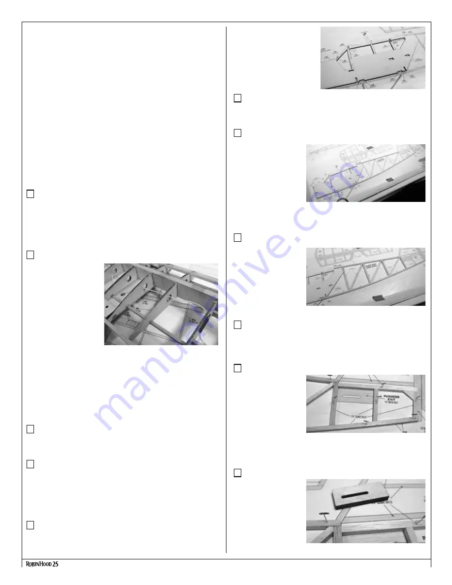
Step 43 - Fuselage Assembly (pushrod exit)

Locate two of the EXIT 

pieces from sheet BP2. 

Glue one on top of 

the other, then pin in 

position and glue into 

place.

Summary of Contents for Robin Hood 25

Page 1: ...ss condition a correctly sized power system and components electronics batteries wheels etc throughout the building process You must correctly install all R C and other components so that the model operates correctly on the ground and in the air Installation shown in the manual is a suggestion You may have to adjust the mounting steps to accommodate the size of your radio equipment You must check ...

Page 2: ...lsa strips 10 pieces 1 4 x 1 2 x 36 balsa strips 1 piece 3 16 x 3 16 36 balsa strips 6 pieces 3 16 x 1 x 36 balsa strips 2 pieces 3 16 x 3 8 x 36 basswood strips 6 pieces 1 1 4 x 6 wooden dowel Hardware parts included in this kit 1 Pre bent landing gear front 1 Pre bent landing gear rear C A type hinges for control surfaces 4 control horns 4 wheel collars 1 8 I D 4 1 8 plastic landing gear straps ...

Page 3: ...e on our website You can either scan the QR code or type this address into your browser www oldschoolmodels com mpics rh25 Let s begin construction by working on the left port wing of your Robinhood 25 Prepare your work area You ll need a flat building surface that is a minimum of 36 long Position the left wing plan over the surface and tape into position Tear off a length of waxed paper long enou...

Page 4: ...de into the holes in both R5 ribs then are glued into position Even if building as a 3 channel we advise installing these Step 12 Wing Assembly attach R3 Locate one R3 rib from BP3 and two WB2 sheer webs from BP4 Position R3 up against the ends of the WB3 pieces from step 10 Once located properly pin the rear tab to the board Lightly tack the R3 to the WB3 pieces Once the glue has set you will cut...

Page 5: ...Once ready the SMR is glued into place spanning the gap between the R5 ribs with the TC towards the inside of the wing Also add glue it to where SMR touches the lower sub spar for a bit of extra support Step 23 Wing Assembly sand R1 flush Take a bit of time to sand the inside edge of the R1 fib flush removing excess length of the spars sub spars leading and trailing edges Step 24 Wing Assembly rig...

Page 6: ...heets Glue one WH7 on top of WH6 on the left side of center making sure that the holes line up then one on the right Now glue a second WH6 on top of the first one on the left side then one on the right Step 30 Wing Assembly center sheeting Now the center sheeting is applied to the underside of the wing s center section Flip the wing so the bottom is facing up and apply the sheeting from the center...

Page 7: ...od 25 wing Now it s time to start construction of the fuselage Prepare your work area Now tape the fuselage side plan and a fresh piece of waxed paper on your building board Step 36 Fuselage Assembly The fuselage sides are made by first constructing the right side then building the left side on top of the right side Because of this you ll need to pay attention to where pins are used during the con...

Page 8: ...pport pieces from 1 4 square strip again using shorter lengths first Take care to match the angles for a good fit Pin these in position and glue into place Step 49 Fuselage Assembly stab support Measure and cut the horizontal support for the stab from 1 4 square strip Pin in position and glue into place Step 50 Fuselage Assembly diagonal supports Measure and cut the diagonal support pieces from 1 ...

Page 9: ...lage Assembly attach H2 or H2A Now is the time to make a choice Will you hold on the front hatch with a couple of screws or with magnets There s not a right or wrong answer and we ve included parts for either scenario If you re using screws locate both H2As from sheet LP1 If you re using magnets locate both H2s from sheet LP1 Whether you choose H2 or H2A they are installed the same way These are p...

Page 10: ... creating rear taper Work now moves to the rear of the fuselage to join the fuselage sides so they taper together To do this you ll need to sand away equal amounts of balsa on the insides of both sides Using a ruler and straight edge measure and draw the guides as shown in the photo 1 2 way on the verticals tapering in about 1 down the fuselage These marks will show exactly how much wood should be...

Page 11: ...and cut the stab s trailing edge from a piece of 1 4 x 1 2 strip Pin this in position Step 80 Stab Elevator S1 install Take the S1 assembly position and glue it in place Step 81 Stab Elevator S2 installs Take one of the S2 assemblies position and glue it in place on the left tip of the stab Then do the same with the other S2 on the right tip of the stab Step 82 Stab Elevator leading edge Measure a...

Page 12: ...and cut the rudder s trailing edge pieces from 1 4 x 1 4 strip Pin and glue in position Step 100 Rudder rudder ribs Measure and cut the rudder s internal ribs from a 1 4 square strip Take care to match the angles for a good fit Pin these in position and glue into place Step 101 Rudder Once the glue has set remove the finished rudder from the plans Step 101 Fuselage Assembly sanding tail pieces Als...

Page 13: ... down Glue one H3 in each of the two slots on the rear of the hatch making sure that the H3 pieces point towards the rear of the hatch as shown Test fit the hatch in place and gently sand the H3 pieces if necessary to give a solid slop free hold If you chose to use magnets glue those in place now If you chose screws fit the hatch in place then using the two pre cut holes in the front of the hatch ...

Page 14: ... carefully and tightly wrap this joint with wire as shown here using We used 26 gauge wire but other thicknesses can be used Starting on one side lightly brush on a bit of flux over the entire wire wrap then use a small torch or a soldering iron to securely older the wire wrap in position securing the front and rear landing gear wires into a solid one piece unit When finished do the same to the ot...

Page 15: ...s the time to attach all the control surfaces to the airframe by gluing the hinges in position attached to the outermost hole on each control horn Finish the installation of your radio gear by adding the receiver flight pack battery and the switch We mounted the receiver to the fuselage side using a bit of self adhesive hook and loop not included The flight pack battery is installed under the TF a...

Page 16: ...eiver pack for your airplane Use the recommended charger supplied with your particular radio system following the instructions provided with the radio In most cases the radio should be charged the night before going out flying Check the radio installation and make sure all the control surfaces are moving correctly i e the correct direction and with the recommended throws Test run the engine and ma...

Page 17: ...Construction Manual www oldschoolmodels com Page 17 APPENDIX A ...

Page 18: ...Page 18 www oldschoolmodels com Construction Manual ...

Reviews: