● Hot and cold water systems approved by the customer for operation.
● Ethernet communication, if any, approved to be used.
● Site manager/customer approval for start of commissioning.
Once installation and commissioning are complete, fill out the
installation and warranty reports.
4.9 Setting up parallel units
1. Start the circulation and open up all throttling valves to the fully open position.
If the circuit is capacity-controlled, make sure the system is running at the
maximum flow.
2. Measure the individual flows and compare to the specified flows.
Measured total flow: m3/h or kg/s.
If the flow notably deviates from the specified flow, search for the reason for this
deviation. Possible reasons can be the pump, filter, valves, pipe length, air, gas,
or dirt in the system.
3. To distribute the flow, start by reducing the flow, where necessary.
●
Measure and adjust all individual flows until correct distribution is achieved.
●
Keep at least one throttling valve fully open, unless the pressure drop is
required to feed a subcooler or other equipment.
If the total flow deviates by 10 % from the specification, all individual flows shall
deviate to the same extent.
Note down all set and measured flows into a copy of the PI diagram.
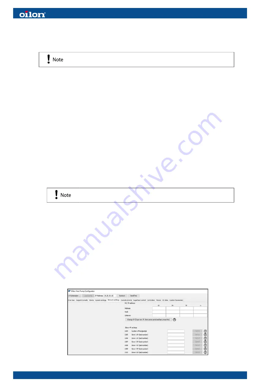
4. For joint control of heat pumps, use OHPC to set it up, first change the IP
addresses of heat pumps so they differ from each other.
Recommended: 10.20.30.11 for the master, 10.20.30.21 for the first slave, 10.20.30.31
for the second slave etc. The first 3 rows (10.20.30) must be the same. You can
choose which will be the master. We recommend the one making the hottest water for
heating, or the one making the coolest water for cooling.
Then connect the heat pumps to each other with a LAN cable between heat pump
tosiboxes, insert a LAN cable in LAN1, LAN2, or LAN3 port.
Then in the master heat pump, set “the number of heat pumps” according to how many
additional heat pumps are being controlled, and set the IP addresses for them.
30 (63)
CHS01 1951EN


