background image

2

3.

OPERATING PRECAUTIONS

This manual contains safety alert symbols and signal words to help prevent injuries 
to the user or damage to property.

 Indications

This indicates there is a chance of death, serious injury or fire if the instructions 

are not followed.

This indicates there is a chance of personal injury or damage to property
if the instructions are not followed.

 Symbols indicating type of danger and preventative measures

This indicates to stop operations.

Unplug power supply from wall outlet.

General caution.

Prohibited operation. Never do this!

Do not disassemble, modify or repair.

Do not touch with wet hands.

WARNING

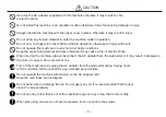
CAUTION

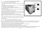
When the earth wire is connected, loosen the screw near the        mark once.
After attaching the earth wire,tighten the screw again.

the bottom of the main body

Summary of Contents for OM-26RB Series

Page 1: ...root co jp HP www ohtake root co jp ATTENTION www ohtake root co jp is the only web site associated with our company We do not have any branches in China Operation Manual Read these instructions for...

Page 2: ...ank you very much for selecting our Automatic Screw Feeder OM 26RB series This machine with the screwing robot can line up screws M 2 M 6 and supplies them continuously to help make screw fastening wo...

Page 3: ...f personal injury or damage to property if the instructions are not followed Symbols indicating type of danger and preventative measures This indicates to stop operations Unplug power supply from wall...

Page 4: ...of fire or explosion Stop operating the machine and unplug the AC adapter from the wall outlet when you detect overheating smoke a pungent odor or any other unusual condition as there may be a risk o...

Page 5: ...ck Do not install this machine in an unstable location otherwise it may fall causing damage or injury When moving the machine always disconnect the AC adapter from the wall outlet or it may result in...

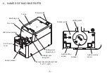
Page 6: ...ing plate Light emitting sensor Light receiving sensor Power switch Front cover Front lower cover Escaper guide Escaper LED screw indicator Sensor bracket Escaper assembly fixing bolts 1 left 1 right...

Page 7: ...6 5 6 A B B C D Passing plate Brush Scraper left Scraper right Rail assembly Rear cover Scooping hopper DC jack Signal line out Timer adjusting knob Amplitude adjusting knob Frequency adjusting knob...

Page 8: ...cated after removing the front cover Screw pick up site Reference table of the specified screws Screw feeder series Screw feeder model Screw size Exchange kit No Rail model No Escaper model No Robot e...

Page 9: ...es and screws are scooped onto the rail The rail vibrates to deliver screws towards the end of the rail then the escaper rotates to deliver screws to the pick up spot When the screws come to the stopp...

Page 10: ...with a screw at the pick up spot but will stop after a certain lapse of time if the screw is not picked up After the screw is picked up the machine starts operating again This time lapse can be varie...

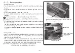
Page 11: ...ent is necessary loosen the brush height adjusting bolt to adjust the brush height If the plastic portion at the front of the brush comes into contact with the passing plate loosen the brush assembly...

Page 12: ...ews are scooped onto the rail for a certain period of time the rail vibration increases If still no screws are scooped on to the rail the machine stops operating Amplitude adjusting knob Timelag adjus...

Page 13: ...mbly either backward or forward After making an adjustment be sure to tighten the rail fixing bolt When the rail comes in contact with the escaper the escaper disk doesn t rotate properly When the cle...

Page 14: ...he adjusting screw is turned counterclockwise the plate moves up Turn OFF the power switch before starting replacement and adjustment Up Down Passing plate Passing plate attaching bolt Loaded screws T...

Page 15: ...e the screws may be caught easily If any adjustment is required loosen the scraper attaching screw and move the scraper plate up or down After such adjustments if deformation on the plate has occurred...

Page 16: ...nals The wires coming out from the back of the machine serves as the detection of presence of screws on the rotational escaper which shall be used with automatic assembly machines or external screw co...

Page 17: ...t This machine is provided with an overload protective circuit Usually the driving motor rotates forward normal rotation to feed loaded screws to the escaper continuously thus picking up screws one af...

Page 18: ...e top of the board Put the signal line out through the line out hole in the cover at the rear Function Screw empty signal high ON Incoming current shall be limited to less than 100mA CAUTION Additiona...

Page 19: ...W D H Weight Approx Kg including rail Screw capacity Approx cc Following accessories Operation Manual 1 copy AC Adapter 1 unit Hexagonal Wrench 1 piece Screwdriver 1 piece Ground Wire 1 piece Power A...

Page 20: ...4 0 8 4 0 11 0 35 6 5 OM 26RB40 4 0 OMR40SET2 OMR40 SIE40 4 0 3 8 4 2 4 5 8 4 5 12 0 35 6 5 OM 26RB50 5 0 OMR50SET2 OMR50 SIE50 OM50 5 0 4 8 5 2 5 5 10 5 5 12 0 35 7 OM 26RB60 6 0 OMR60SET2 OMR60 SIE...

Page 21: ...mm To sensor pick pioint DC jack A 2 0 13 7 2 3 13 9 2 6 14 0 3 0 14 2 3 5 14 5 4 0 14 7 5 0 15 2 6 0 15 7 Screw size Approximate measurement of A 2 0 13 7 2 3 13 9 2 6 14 0 3 0 14 2 3 5 14 5 4 0 14...

Page 22: ...abor regardless of the terms of warranty Failure due to improper handling Failure due to product modification or improper processing Failure due to causes beyond control for example earthquake or fire...

Page 23: ...22...

Page 24: ...KOGYO CO LTD 27 021 0902 Tel 0191 24 3144 Fax 0191 24 3145 27 Kangasaki Hagisyou Ichinoseki Iwate 021 0902 JAPAN Tel 81 191 24 3144 Fax 81 191 24 3145 http www ohtake root co jp as of November 2014 20...

Reviews: