background image

SonarMite DFX v1.20 (c) Lymtech 2016 

Page 

9

 of 

26


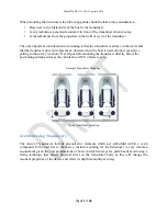
Range and Bearing from hand held laser plus Tide plus Time 


Simple event marking past known position markers 


The  basis  on  which  all  data  correlation  is  achieved  is  internal  time  base,  so  particularly  when 
using the SonarMite with  GPS data the data logger  clock should be  synchronized  to  GPS time 
(UTC).  

Sound Velocity Settings 

 
The SonarMite default Speed of Sound in Water(SoS) setting is 1500m/second,  facilities to vary 
this  have  been  provided  in  the  calibration  or  in  post  processing.  In  practice  this  velocity  value 
can vary due to several factors … 


Water Temperature 


Water Salinity 


Water Turbidity 


All of the above factors vary the density of the water in some way and effect the „time of flight‟ 
of a pulse of ultrasound in water and hence the depth calculated from this time by the SonarMite. 
The  user  can  either  measure  the  speed  of  sound  in  water  by  taking  velocity  profiles  using  a 
dedicated velocity measuring device or can use the SonarMite static over a known depth to a flat, 
firm base and then compare the measured value with the known depth. The difference in Sound 
Velocity between warm fresh water and cold salt water is about +/-30m/Second which represents 
a change of depth of +/-2%, this must be viewed in context with typical depths of the survey, if a 
typical  depth  is  10m  then  the  error  could  be  about  20cm. 

The  Sound  Velocity  setting  is  the 

largest source of measurement error when care is not taken in setting it correctly. 

Reverse Voltage Protection 

 
The  SonarMite  DFX  is  protected  from  reverse  connection  or  direct  short  circuit  by  an  internal 
diode and 1 Amp thermal fuse. If the fuse is tripped then the system will need to be disconnected 
for 1 minute for the fuse to cool down and reset itself.  

Weatherproofing 

 
The  SonarMite  has  been  designed  to  conform  to  the  IP65  waterproofing  standard,  this 
benchmark  describes  equipment  which  can  withstand  a  light  spray  of  water  from  a  hose  for  a 
short period of time, it does not imply the device is suitable for immersion in any depth of water 
or  exposed  to  prolonged  harsh  weather  conditions.  The  weatherproofing  also  assumes  the 
connectors or cover caps are fully screwed on to their rubber sealing rings. The weatherproofing 
does not apply to certain components which are by definition not designed for outdoor use such 
as the D9 serial or USB cable connectors.  

Summary of Contents for SONARMITE DFX dual beam

Page 1: ...e products in the field of instrumentation and software used within the Earth Science sectors Achievements to date include DGM the first digital ground modelling software to run on a standard PC SONAR...

Page 2: ...locity Settings 9 Reverse Voltage Protection 9 Weatherproofing 9 DEPTH TRANSDUCER 10 Transducer Mounting 10 Avoid Stressing Transducers 11 BLUETOOTH INTERFACE 12 BlueTooth ID Password code 12 Bluetoot...

Page 3: ...mmands 17 H elp 17 Memory Operations 17 R eset 17 L oad 18 S ave 18 General Operations 18 Query format 18 F ormat 19 V ersion 23 I d 23 U p 23 D own 23 C lear 23 B 23 Transducer Specification 24 Trans...

Page 4: ...ith new measurement technologies Throughout the Hydrographic world the term Black Box has become a euphemism for a device that has a minimal user interface and normally requires connection to a PC to...

Page 5: ...frequency performace does not reflect from small objects in the water column and it will indicate areas of soft bottom Can mud thickness can be measured with Dual Frequency The residual difference be...

Page 6: ...d in resin and have no serviceable parts The connecting cable to the transducer carries only low DC voltage and digital I O none of the EMC problems associated with conventional analogue sonar devices...

Page 7: ...r to detail pole Portable internal NiMh battery pack and charger SonarMite DFX dual beam echo sounder The SonarMite DFX is a compact portable low power system for use in shallow water hydrographic sur...

Page 8: ...d the parallel Bluetooth output for graphic depth display Typical bow transducer mounting Switching the System On To turn the system on the user ensures the system is connected to a battery then conne...

Page 9: ...he known depth The difference in Sound Velocity between warm fresh water and cold salt water is about 30m Second which represents a change of depth of 2 this must be viewed in context with typical dep...

Page 10: ...il pole The transducer includes a unique processor and is not the same device as the commercially available transducers Hydrodynamic shape provides vertical sound beam orientation Chemical and impact...

Page 11: ...used at higher speeds i e getting to the survey location If at all possible mounting the transducer directly below the positioning antenna reduces the calculation of X Y offsets to zero Example Trans...

Page 12: ...assword code In some instances the local Bluetooth interface may request a password ID to set up pairing with the device for DFX SPX version devices the pin number is always set to 1234 numeric one tw...

Page 13: ...DA The Bluetooth Serial Terminal will connect to any Bluetooth enabled device supporting SPP This can be in MASTER mode where the terminal initiates the connection or SLAVE mode where the remote devic...

Page 14: ...adaptor cable Using the slower baud rate of 4800 allows the serial cable to be extended so that the computer can be up to 20m away from the echo sounder Communication with the SonarMite over any of t...

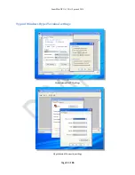
Page 15: ...SonarMite DFX v1 20 c Lymtech 2016 Page 15 of 26 Typical Windows HyperTerminal settings Hyperterminal ASCII settings Hyperterminal Connection settings...

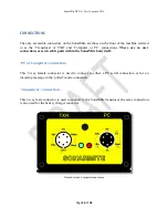
Page 16: ...er connections or serviceable parts within the SonarMite body itself PC or Computer connection This 6 way female connector is used to connect to either a PC serial connection or for an incoming messag...

Page 17: ...ng any of the configuration command characters will only change the current active states enabling the user to sample output unil the Save command is used to store the current settings and make them t...

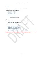
Page 18: ...ly available in the SYS output mode S ave Pressing S Contol S will save the current working memory area to Flash memory to become the system settings on reboot General Operations Query format Pressing...

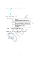
Page 19: ...ID integer six numeric ASCII parameters floating format space delimited as id hdepth ldepth wtemp battery flags cr lf where id The id number of the instrument 0 7 hdepth current hi freq measured depth...

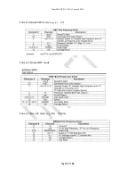
Page 20: ...7 94 18 48 17 96 18 54 18 00 18 60 18 01 18 65 18 05 18 69 18 09 Example Simple ASCII Output Format 2 DBS NMEA mode Format 3 DPT NMEA mode e g SMDPT 1 81 0 0 66 SLDPT 16 68 0 0 72 SHDPT 17 53 0 0 7F S...

Page 21: ...SonarMite DFX v1 20 c Lymtech 2016 Page 21 of 26 Format 4 Odom SBT mode e g et 47 Format 5 Odom DBT mode Format 6 Deso 25 mode e g DA 0 48 m...

Page 22: ...DHI D 30 28 M XDLO C 15 15 C WTHI 71 SDXDR D 30 95 M XDHI D 30 28 M XDLO C 15 15 C WTHI 71 Example Raw Data Output Format 8 Old SonarMite format e g 1 1 88 12 7 128 20 1 30 16 0 0 0 10 9 100 7 1 29 43...

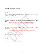
Page 23: ...U p Increase the sound velocity setting for dense cold water only available in the SYS output mode This is a dangerous function and will change calibration values if saved D own Decrease the sound vel...

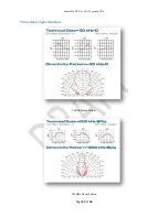
Page 24: ...SonarMite DFX v1 20 c Lymtech 2016 Page 24 of 26 Transducer Specification 30KHz Beam Pattern 200KHz Beam Pattern...

Page 25: ...Kg Transducer Lo Frequency 30 KHz Active Transducer Beam Spread 8 to 30 Degrees Depth Range 1 2m to 200 0m Software limited Accuracy 0 130m RMS Weight 2 4 Kg Data Output Range 2Hz Ultrasonic Ping Rate...

Page 26: ...SonarMite DFX v1 20 c Lymtech 2016 Page 26 of 26 WIRING DIAGRAMS...

Reviews: