background image

PAGE 8 OF 30

0908 IH-606

H-606

9

2.5 Connecting Power

The CD-11 Indicator may be operated using the AC Adapter supplied, or 6 Alkaline C-type batteries (not supplied).

2.5.1 AC Adapter

• Connect the AC Adapter connector to the receptacle located at the right-hand side of the Indicator and plug the

adapter into a convenient outlet.

NOTICE:

The socket/outlet must be installed near

the equipment and shall be easily accessible.

2.4 Cautionary Notes

• Model CD-11 Indicator 

must not be operated in hazardous areas

 with the standard-supplied AC adapter.

• Before connecting the AC adapter, verify that the voltage printed on it corresponds to the local mains voltage.  If

this is not the case, please contact your local Ohaus dealer.

• Model CD-11 Indicator may only be used in a dry environment.

2.5.2 Battery Installation

Open the battery cover on the bottom of the housing.

Insert 6 Alkaline C-type batteries into the two battery sleeves (3 in each sleeve) making sure the batteries are

all facing in the same direction.

Place the batteries into the two slots in the housing.  Orient the batteries so that the positive (+) ends are

against the reeds and the negative (-) ends rest against the springs.

NOTE

:  It is recommended that when the CD-11 is operated from batteries, the Auto-Off Timer feature be turned on

   to extend battery life.  When setting up the Indicator, refer to Intial Setup,Readout menu, paragraph 2.7.5.

2.5.3  Operating the Indicator

Once the Indicator and Scale Base are connected and installed, follow the setup procedure outlined below.

2.6 Setup Protection

The CD-11 Indicator is equipped with menus which permit certain functions to be locked out (not changed) during

operation. If you intend to lock out changes to the setup selections you make, 

do not

 re-assemble the indicator.  You

will need to access the menu lockout jumper located on the circuit board following the setup procedure.  Keep the

four case screws in a safe place until you have completed the setup procedure for the Indicator.  Once you have

completed all setup procedures, you may replace the four case screws.

Power On/Off

• With the Indicator connected to an appropriate power supply, press the 

On/Off

 button. The Indicator performs a

self-test, indicates the software revision momentarily and then goes to a weighing mode. At this point, the Indica-

tor is on and ready for initial setup.

Stabilization

Before initially using the Indicator, allow time for it to adjust to its new environment.  Recommended warm up period is

five (5) minutes.

CD-11 Indicator

10

2.7 Initial Setup

For first time setup, step through all menus and set the parameters as desired.  As the last step, enter the CAL menu

and calibrate the system.

The indicator has five menus; CAL, SETUP, READ, PRINT and LOCSW which are entered by pressing and holding

the

Zero/Menu

 button until MENU is displayed, then releasing it.  The display then switches to CAL.  To access the

rest of the menus, the 

Print/Units

 button is repeatedly pressed until the desired menu is reached.

Print/Units Button

Change between menus horizontally or change sub-menu parameters.

Zero/Menu Button

Press and hold to enter menu.  Enters menu and steps through sub-menus vertically.

2.7.1 Control Functions

During setup, only the 

Print/Units

 and

 Zero/Menu

 buttons are used.

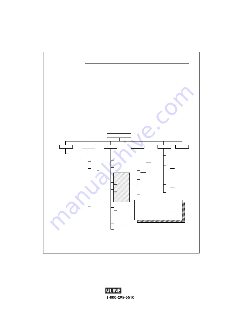
2.7.2 Menu Structure

The following table illustrates the menu structure in the CD-11 Indicator.

MAIN MENU

CAL

SEtuP

rEAd

Print

LocSW

CALIBRATION
Perform

Legal for Trade

ON or 

OFF

Zero

2%

,18%, 100%

Calibration Unit

lb or 

kg

Full Scale

capacity

5, 10, 20, 25,

30, 40, 50, 60...

Graduation Size

.001, .002, .005

.01, .02, .05, .1,

.2, .5, 2, 5

Calibration Point

5, 10......

End/Store

Settings

* Reset N or Y

to Factory Settings

* Averaging Level

HI or 

LO

* Stability Level

0.5,

1,

 or 3

*Unit g switch

ON or 

OFF

*Unit kg switch

ON

 or OFF

*Unit lb switch

ON

 or OFF

*Parts Counting

switch

ON or 

OFF

*Auto Zero

Tracking

0.5

, 1 or 3

*Auto Off Timer

ON (5 min) or 

OFF

*Retain Zero Data

ON or 

OFF

* End/Store

Settings

* Reset

to Factory Settings

* Baud Rate set

1200,

2400

, 4800

9600

*Parity Bit set

NONE

, Even, or

Odd

*Data Length set

7

 or 8

*Stop Bits set

1 or 

2

* End/Store

Settings

SETUP Lockout

Switch set

ON,

OFF

* READOUT

Lockout Switch set

ON,

OFF

* PRINT Lockout

Switch set

ON,

OFF

CALIBRATION

Lockout Switch set

ON,

OFF

* End/Store

Settings

Press (

Zero/Menu

) to enter the display

sumenu or select a displayed setting.

Press (

Print/Units

) to change the displayed submenu or setting.

Factory default settings are shown in 

underlined and boldface

 type.

When jumper (CAL) on the circuit board is opened, all of the menus

can be reached except CALIBRATION Menu, but only the submenus

which are marked ' * ' can be setup, see menu structure.

Quit

NOTE

: For details about units in shaded

           area, refer to paragraph 4.7.

CD-11 Indicator

Summary of Contents for CD-11

Page 1: ...Oh Declaration of Conformity CE are in conformity with Konformitätserkärung W mit CE mit den genannte Déclaration de conformité munis de la mention CE Declaración de Conformid indicados a continuación c Dichiarazione di conformit seguito contrassegnati con Instrument Type Waagentyp Marked with Gekennzeichnet mit Munis de la mention Con el distintivo Contrassegnati con la Marcatura H 606 Deluxe Ben...

Page 2: ... 3 Connecting the Indicator to a Scale Base 8 2 4 Cautionary Notes 9 2 5 Connecting Power 9 2 5 1 AC Adapter 9 2 5 2 Battery Installation 9 2 5 3 Operating the Indicator 9 2 6 Setup Protection 9 2 7 Initial Setup 10 2 7 1 Control Functions 10 2 7 2 Menu Structure 10 2 7 3 Load Cell Capacity Information 11 2 7 4 Setup Menu 12 2 7 5 Readout Menu 13 2 7 6 Print menu 16 2 7 7 Lockout Switch Menu 17 2 ...

Page 3: ...4 12 RS232 Commands 25 4 12 1 Output Formats 25 4 13 Printing Data 25 5 CARE AND MAINTENANCE 26 5 1 Troubleshooting 26 5 2 Error Codes List 27 5 3 Service Information 27 5 4 Replacement Parts 27 5 5 Accessories 27 5 6 Technical Data 27 CD 11 Indicator OVERVIEW OF CO No Designation 1 Display 2 Stable 3 Center of Zero 4 ON OFF button 5 Pcs 6 Print Units butto 7 Gross Brutto 8 Zero Menu butt 9 Net 10...

Page 4: ...int Units button Short press prints data which is displayed on the Indicator Long press changes unit of measure 7 Gross Brutto LCD indicator prompt indicates gross weight 8 Zero Menu button When pressed zero s display Long press allows entry into menus 9 Net LCD indicator prompt indicates net weight 10 G N T button Repeated presses select either gross net or tare weight to be displayed Tare Long p...

Page 5: ...ernally using the AC adapter sup plied A six digit LCD display is 1 0 inches 2 5 centimeters in height provides easy visibility when working at dis tances from the indicator Four switches mounted on the front panel enable simple set up procedures A menu lockout switch can be set to lock out various functions of the indicator to prevent settings from being changed An RS232 Interface is built in Acc...

Page 6: ...ge machinery Maximum accuracy will be achieved when the area is clean and vibration free 2 3 Connecting the Indicator to a Scale Base Turn the Indicator over and using a screw driver remove the four screws which secure the rear cover Two screws are under the battery box s cap Remove the rear cover Remove batteries if installed Pass the load cell cable through the liquid tight connector on the left...

Page 7: ...etup Readout menu paragraph 2 7 5 2 5 3 Operating the Indicator Once the Indicator and Scale Base are connected and installed follow the setup procedure outlined below 2 6 Setup Protection The CD 11 Indicator is equipped with menus which permit certain functions to be locked out not changed during operation If you intend to lock out changes to the setup selections you make do not re assemble the i...

Page 8: ... Menu Structure The following table illustrates the menu structure in the CD 11 Indicator MAIN MENU CAL SEtuP rEAd Print LocSW CALIBRATION Perform Legal for Trade ON or OFF Zero 2 18 100 Calibration Unit lb or kg Full Scale capacity 5 10 20 25 30 40 50 60 Graduation Size 001 002 005 01 02 05 1 2 5 2 5 Calibration Point 5 10 End Store Settings Reset N or Y to Factory Settings Averaging Level HI or ...

Page 9: ... 2000d 2500d 3000d 4000d 5000d 6000d 7500d 10000d 20000d 0 001 5 10 20 0 002 10 20 40 0 005 5 10 20 25 30 50 100 0 005 5 6 7 5 10 12 5 15 20 25 30 37 5 50 100 0 01 10 20 25 30 40 50 60 75 100 200 0 02 20 30 40 50 60 100 120 150 200 400 0 05 50 60 75 100 150 200 250 300 500 1000 0 1 100 120 150 200 250 300 400 500 600 750 1000 2000 0 2 200 300 400 500 600 1000 1500 2000 0 5 500 600 750 1000 1500 20...

Page 10: ...o 2 18 zero operating range is 2 to 18 100 zero operation range is 2 to 100 NOTE If LFT is ON only 2 and 18 are available Press Print Units button and select either 2 18 or 100 Press Zero Menu button CAL Un kg is displayed This is the calibration unit setting Selections are lb calibration unit is lb kg calibration unit is kg Press Print Units button and select either kg or lb Press Zero Menu F xx ...

Page 11: ... level compensates for vibration or excessive air currents on the scale base During operation the indicator continually takes weight readings from the load cell Successive readings are then digitally processed to achieve a stabilized display Using this feature you specify how much processing you need HI and LO settings are available HI setting More processing greater stability and slower stabiliza...

Page 12: ...table condition 0 5 d smallest range stability indicator is ON only when displayed weight is stable within 0 5 divisions 1 d stable within 1 division 3 d largest range stabil ity indicator is ON even though displayed weight changes 3 divisions Factory default setting is 1 Press Print Units button and select 0 5 1 or 3 Normal 1d stability is default recommended UNITS SELECTION Press Zero Menu butto...

Page 13: ...On the Indicator stores the current zero point and restores it on the power up Press Print Units button and select ON or OFF OFF is the default setting Press Zero Menu button to end this block END is displayed Press Zero Menu button Print is displayed which is the next menu or press Print Units button to go back to Readout menu If initial setup go to the next paragraph To exit from the Setup press...

Page 14: ... This allows resetting the Print menu to factory defaults rESETn no does not reset settings rESETy yes will reset the entire Print menu as follows Baud rate 2400 parity none data length 7 stop bit 2 Press Print Units button and select N or Y Press Zero Menu button bd2400 displayed Press Print Units button and select desired baud rate Baud rate selections are 1200 2400 4800 and 9600 2400 is the def...

Page 15: ...ed Press Print Units button and select ON or OFF Press Zero Menu button LPtOFF is displayed This permits locking the Print menu OFF is unlocked ON is read only locked Press Print Units button and select ON or OFF Press Zero Menu button LCLOFF is displayed This permits locking the Calibration menu OFF is un locked ON is read only locked This menu is hid den if the CAL jumper is off Press Print Unit...

Page 16: ...cover of the Indicator should CAL jumper CD 11 Indicator 18 CD 11 Indicators are equipped with a standard IBMTM compatible bi directional RS232 interface for communi cation with printers and computers When the Indicator is connected directly to a printer or Programmable Logic Controller PLC displayed data can be recorded at any time by simply pressing the PRINT UNITS button Connecting the Indicato...

Page 17: ...isplayed Press Zero Menu button C is displayed The scale base MUST be stable during this period and is establishing a zero point After a few seconds the requested weight value is displayed The sample illustration indicates a 30kg scale Cal Point CP was set for 30kg Place the indicated mass on the platform Keep the platform stable during this period Press Zero Menu button C is displayed while the I...

Page 18: ...MUST be calibrated prior to performing this proceedure Procedure Perform the procedure in paragraph 2 7 7 and set all menu items ON This effectively locks out all menus from being changed but can be viewed Remove the front cover from the Indicator to expose the PC board tilt it back Be careful as the cover is connected to the PC board by a flexible cable Refer to the illustration on the left and n...

Page 19: ...removed from the scale the Net weight is displayed as a negative value 4 1 Turning On Indicator Press and hold On Off button until the LCD display appears then release On Off button The display momentarily displays segment check the software revision of the Indicator and then goes into a weigh ing mode If the Indicator has been properly set up and connected the display should be as shown to the le...

Page 20: ...rE is displayed then release button Stable 4 5 Gross Net Tare Recall Operation Gross Stable When a container has been placed on the platform and tared it s weight is stored in memory Adding material to the container is shown as NET weight The gross weight is a combination of the tared weight and the material The G N T Tare button allows switching between GROSS NET and TARE weights Repeately press ...

Page 21: ...0 2 0 1 N A 0 5 1 N A 1 2 N A 2 5 N A 5 N A N A 4 8 Parts Counting Operation Parts counting is enabled only when turned ON in the Readout menu Refer to paragraph 2 7 5 In the parts counting mode the Indicator displays the quanitity of parts placed on the platform The Indicator determines the quanitity based on the average weight of a single part All parts must be reasonably uniform in weight for a...

Page 22: ...iner is used be sure to tare the empty container first Additional samples may be added to the platform as long as the same sample weight intially entered is used with the samples being weighed Pcs Gross Brutto Pcs Gross Brutto Pcs Gross Brutto Pcs Gross Brutto Stable 4 10 Returning to a Weighing Mode Press Print Units button until the display indicates the desired measuring unit either kg lb or g ...

Page 23: ...d CRLF 4 12 1 Output Formats Data output can be initiated in one of two ways 1 By pressing Print Units button 2 Sending a print command P from a computer or a PLC The output format is illustrated in the RS232 command table which follows Command Character Description Print current mode g kg lb 0S Send weight stable or unstable 1S Send stable weight only AS Auto send data when stable after motion Z ...

Page 24: ... base to less than entered zero Change allowable zero in ZERO parameter of Setup menu Normal operation when this feature is enabled Remove disturbances or reduce motion Increase AZT level in readout menu Increase averaging level in readout menu Enable desired unit in Readout menu See paragraph 2 7 5 Conversion to large typically in g Verify communication parameters Check cable connections Check co...

Page 25: ...ac 60 Hz 80500435 AC Adapter Continental Europe 196 253 V ac 50 Hz 80500436 AC Adapter UK 196 264 V ac 50 Hz 80500437 5 5 Accessories Description Ohaus Part No Adjustable Column 80250632 Wall Mounting Bracket 80250633 Scale Base Mounting Plate 80250686 RS232 Interface Cable Printer 80500432 RS232 Interface Cable PC 25 Pin 80500431 RS232 Interface Cable PC 9 Pin 80500433 Printer AS142 5 6 Technical...

Page 26: ...capture range 0 5 1 or 3 divisions Zeroing range 2 18 or 100 of capacity Span calibration push button selectable from 20 to 100 of scale base capacity Weighing system Analog strain gauge load cell Load cell excitation voltage 5V dc Load cell input sensitivity Up to 3mV V Load cell drive 60 mA at 5V dc drives up to 4 x 350 ohm load cells Display in cm LCD 1 0 25 4 Power AC Adapter 100 120 220 240 V...

Page 27: ... 606 H 606 ship from the date of riod Ohaus will repair charge provided that or misuse exposed to side of the product or erly returned warranty he authorized dealer Corporation shall not ase contact Ohaus or CD 11 Indicator ...

Page 28: ...PAGE 28 OF 30 0908 IH 606 H 606 ...

Page 29: ...GE 29 OF 30 0908 IH 606 H 606 BEFORE CALIBRATION OR USE REMOVE THE RED PLASTIC SHIPPING TABS IN THE CORNERS OF THE SCALE BASE Remove Shipping Spacers Do Not Remove Screws Four Overload Bolts Factory Setup ...

Page 30: ...PAGE 30 OF 30 0908 IH 606 E RED PLASTIC ALE BASE move Shipping Spacers o Not Remove Screws Four Overload Bolts Factory Setup ...

Reviews: