background image

3- 9 Digital Filter

3- 9 Digital Filter

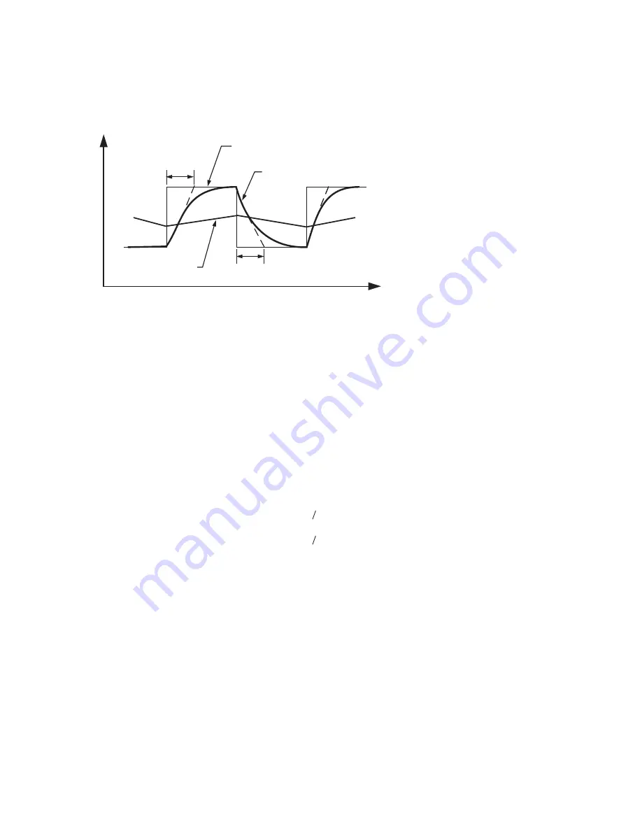
In certain applications, the process value is too unstable to be read. To improve this, a programmable low pass filter
incorporated in the controller can be used. This is a first order filter with time constant specified by FILT parameter .
The default value of FILT is 0.5 sec. before shipping. Adjust FILT to change the time constant from 0 to 60 seconds. 0
seconds represents no filter is applied to the input signal. The filter is characterized by the following diagram.

Time

PV

1 sec

1 sec

1 sec

1 sec

FILT=30

FILT=0

FILT=1

Figure 3.8
Filter Characteristics

Figure 3.8
Filter Characteristics

The Filter is available only for PV, and is performed for the displayed value only. The controller is designed to use an
unfiltered signal for control even if a Filter is applied. A lagged ( filtered ) signal, if used for control, may produce an
unstable process.

The Filter is available only for PV, and is performed for the displayed value only. The controller is designed to use an
unfiltered signal for control even if a Filter is applied. A lagged ( filtered ) signal, if used for control, may produce an
unstable process.

Note:

25

3 -10 Failure Transfer

3 -10 Failure Transfer

The controller will enter failure mode as one of the following conditions occurs:
1.

occurs due to the input sensor break or input current below 1mA if 4-20 mA is selected or input voltage below

0.25V if 1-5 V is selected .

2.

occurs due to the A-D converter of the controller fails.

SBER

ADER

The controller will enter failure mode as one of the following conditions occurs:
1.

occurs due to the input sensor break or input current below 1mA if 4-20 mA is selected or input voltage below

0.25V if 1-5 V is selected .

2.

occurs due to the A-D converter of the controller fails.

SBER

ADER

The output 1 and output 2 will perform the failure transfer function as the controller enters failure mode.

The output 1 and output 2 will perform the failure transfer function as the controller enters failure mode.

Output 2 Failure Transfer, if activated, will perform :
1. If OUT2 is configured as COOL, and BPLS is selected for O2FT, then output 2 will perform bumpless transfer.

Thereafter the previous averaging value of MV2 will be used for controlling output 2.

2. If OUT2 is configured as COOL, and a value of 0 to 100.0 % is set for O2FT,

then output 2 will perform failure transfer. Thereafter the value of O2FT will be used for controlling output 2.

3. If OUT2 is configured as alarm function, and OFF is set for O2FT, then

output 2 will transfer to off state, otherwise, output 2 will transfer to on state if ON is set for O2FT.

Output 1 Failure Transfer, if activated, will perform :
1. If output 1 is configured as proportional control ( PB=0 ), and BPLS is selected for O1FT, then output 1 will perform

bumpless transfer. Thereafter the previous control output value (MV1) will be used for controlling output 1.

2. If output 1 is configured as proportional control ( PB=0 ), and a value of 0 to 100.0 % is set for O1FT, then output 1

will perform failure transfer. Thereafter the value of O1FT will be used for controlling output 1.

3. If output 1 is configured as ON-OFF control ( PB=0 ), then output 1 will transfer to off state if OFF is set for O1FT

and transfer to on state if ON is set for O1FT.

Summary of Contents for ETR-3000

Page 1: ...PK486 OMC59 SOFTWARE VERSION 33 16 and HIGHER INSTRUCTION MANUAL Model ETR 3000 AUTOMATIC TUNING 1 32 DIN SMARTER LOGIC Controller SMARTER SMARTER LOGIC LOGIC LOGIC...

Page 2: ...or ETR 3 which will shut down the equipment at a preset process condition in order to preclude any possible damage to individual components or system It is strongly recommended that a process incorpor...

Page 3: ...tallation Guidlines 15 2 6 Sensor Input Wiring 15 2 7 Control Output Wiring 16 2 8 Alarm Wiring 17 2 9 Data Communication 18 3 1 Lockout 19 3 2 Signal Input 19 3 3 Control Outputs 20 3 4 Alarm 22 3 5...

Page 4: ...fast processes Digital communications RS 485 or RS 232 are available as an additional option This option allows the units to be integrated with a supervisory control system and or software A programm...

Page 5: ...new system A clever algorithm is provided to obtain an optimal set of control parameters for the process The Auto tune feature can be applied either as the process is warming up cold start or as the p...

Page 6: ...S 485 or RS 422 to RS 232 network SNA10A Smart Network Adaptor for third party software which converts 255 channels of RS 485 or RS 422 to RS 232 Network SNA10A Smart Network Adaptor for third party s...

Page 7: ...is used to increase the value of a selected parameter This key is used to decrease the value of a selected parameter This key is used to 1 Revert the controllers display back to the process value or s...

Page 8: ...h it displays the Program code and version of the controller The left diagram shows program no 34 for an ETR 3000 version 16 Displays the program code of the product for 2 5 seconds Figure 1 4 Display...

Page 9: ...3 seconds then release to enter the calibration menu 1 2 2 sec LOCK INPT UNIT DP INLO SP1L INHI SP1H SHIF FILT DISP OUT1 O1TY O1FT O1HY CYC1 PB TI TD OFST RAMP RR OUT2 O2TY O2FT O2HY CYC2 CPB DB ALMD...

Page 10: ...0 J type T C Range UNIT Input unit selection 0 Degree C unit 1 Degree F unit 2 Process unit 0 1 DP Decimal point selection 1 0 No decimal point 1 1 decimal digit 2 2 decimal digits 3 3 decimal digits...

Page 11: ...m 6 Process High Alarm 7 Process Low Alarm 8 Cooling PID Function 2 RAMP Ramp function selection 0 No Function 1 Use unit minute 2 Use unit hour 0 1 Dwell timer action 4 Deviation out of band Alarm 5...

Page 12: ...Retransmission low scale value Low 19999 High 45536 0 0 C 32 0 F REHI Retransmission high scale value Low 19999 High 45536 212 0 F 100 0 C SEL1 Select 1 st parameter for user menu 0 No parameter sele...

Page 13: ...n the model number serial number and date code for future reference when corresponding with our service center The serial number S N and date code D C are labeled on the box and the housing of control...

Page 14: ...r while checking Care must be taken to ensure that maximum voltage rating specified on the label are not exceeded It is recommended that power of these units to be protected by fuses or circuit breake...

Page 15: ...more than one thermocouple in parallel can provide an average temperature readout and produce better results in most air heated processes Proper sensor installation can eliminate many problems in a co...

Page 16: ...Heater Load Three Phase Delta Heater Load Contactor 5 6 _ Load 120V 240V Main Supply 120V 240V Main Supply SSR 30mA 14Vdc or 30mA 5Vdc Pulsed Voltage 30mA 14Vdc or 30mA 5Vdc Pulsed Voltage Internal Ci...

Page 17: ...l Circuit Internal Circuit 5V 0V 33 33 _ _ 3 4 Maximum Load 500 ohms Maximum Load 500 ohms 0 20mA 4 20mA 0 20mA 4 20mA _ Load 3 4 Figure 2 15 Output 2 Linear Voltage Figure 2 15 Output 2 Linear Voltag...

Page 18: ...XD RXD COM 12 13 11 Using RS 232 communications as shown above right a special cable CC 94 1 should be used The other option is to configure a 9 pin serial cable as shown below Using RS 232 communicat...

Page 19: ...e PV INLO SL SH S input signal Figure 3 1 Conversion Curve for Linear Type Process Value Figure 3 1 Conversion Curve for Linear Type Process Value Formula PV INLO INH INLO Formula PV INLO INH INLO S S...

Page 20: ...nual reset if PB is not equal to 0 OFST is measured by with range 0 100 0 In the steady state ie process has been stabilized if the process value is lower than the set point by a definite value say 5...

Page 21: ...of PB with range 50 300 Initially set 100 for CPB and examine the cooling effect If cooling action should be enhanced then decrease CPB if cooling action is too strong then increase CPB The value of C...

Page 22: ...iation band alarm SV SP2 SV SP2 DB HI DB LO A presets two trigger levels relative to the set point The two trigger levels are and for alarm When the process is higher than SV SP2 or lower than SV SP2...

Page 23: ...n as failure mode manual control mode the auto tuning mode or the calibration mode is entered Example without Dwell Timer Example without Dwell Timer Select MINR for RAMP selects C for UNIT selects 1...

Page 24: ...Heater Adjust SHIF SHIF 35 C Supply more heat 200 C C Heat Transfer 235 C Sensor Subject Heater Display is stable SHIF 35 C PV SV Figure 3 7 PV Shift Application Figure 3 7 PV Shift Application Here i...

Page 25: ...form the failure transfer function as the controller enters failure mode Output 2 Failure Transfer if activated will perform 1 If OUT2 is configured as COOL and BPLS is selected for O2FT then output 2...

Page 26: ...rating value or a lower value if overshooting beyond the normal process value is likely to cause damage NOTE NOTE The ramping function if used will be disabled once auto tuning is initiated The rampin...

Page 27: ...Oscillations Slow Response or Oscillations Instability or Oscillations Instability or Oscillations High Overshoot High Overshoot Decrease PB Decrease PB Increase PB Increase PB Decrease TI Decrease TI...

Page 28: ...5 port a network adaptor such as has to be used to convert RS 485 to RS 232 for a PC if RS 485 is required for the data communication But there is no need to be sad Many RS 485 units up to 247 units c...

Page 29: ...imer ALM Heater T C Oven 6 4 3 OUT1 Set SP1 150 0 SP2 30 0 SP1 150 0 SP2 30 0 4 1 Heat Only Control with Dwell Timer 4 1 Heat Only Control with Dwell Timer An oven is designed to dry products at 150 d...

Page 30: ...efrigerator at a temperature below 0 The temperature is lower than the ambient therefore a cooling action is required Select DIRT for OUT1 Since output 1 is used to drive a magnetic contactor O1TY sho...

Page 31: ...media instead of oil the CPB is set at 250 If air is used as cooling media instead of oil the CPB is set at 100 Adjustment of DB is dependent on the system requirements More positive value of DB will...

Page 32: ...nce the controller needs 30 minutes to warm up an unit before calibration calibrating the unit one by one is quite inefficient An automatic calibration system for numerous quantities is available upon...

Page 33: ...st 20 minutes in still air room room temperature 25 3 C Figure 5 2 Cold Junction Calibration Setup Figure 5 2 Cold Junction Calibration Setup 9 10 K K 5520A Calibrator 5520A Calibrator K TC The 5520A...

Page 34: ...modification and recalibration procedures for a linear voltage or a linear current input 1 Remove R60 3 3K and install two 1 4 W resistors RA and RB on the control board with the recommended values s...

Page 35: ...cond for 4 20 mA and 1 5 V inputs Resolution Sampling Rate Maximum Rating Temperature Effect Sensor Lead Resistance Effect 18 bits 5 times second 2 VDC minimum 12 VDC maximum 1 minute for mA input 1 5...

Page 36: ...0 C 346 F 1292 F 210 C 700 C 346 F 1292 F 8mV 70mV 3mA 27mA 1 3V 11 5V 0 05 0 05 0 05 0 05 70 5 1 3 K 1 3 K 1 3 K 1 3 K 1 3 K 1 3 K 650 K 650 K 2 2 M 2 2 M 2 2 M 2 2 M 2 2 M 2 2 M 2 2 M 2 2 M 2 2 M 2...

Page 37: ...viation High Low Alarm Deviation Band High Low Alarm PV High Low Alarm PID cooling control Normal Latching Hold Latching Hold 0 1 4553 6 minutes Output 2 Functions Alarm Mode Dwell Timer Dwell timer D...

Page 38: ...and Cool MV2 Cold start and warm start Auto transfer to manual mode while sensor break or A D converter damage 0 900 0 F minute or 0 900 0 F hour ramp rate Digital Filter Digital Filter Function Time...

Page 39: ...able to enforce such warranty it being understood Ogden shall have no obligation to initiate litigation unless Buyer undertakes to pay all cost and expenses therefor including but not limited to atto...

Page 40: ...847 593 8050 Fax 847 593 8062 www ogdenmfg com Ogden Manufacturing Co 2004 OGDEN SMARTER LOGIC ETR and ETR 9000 are Registered Trademarks of Ogden Manufacturing Co MARCA REGISTRADA Specifications sub...

Reviews: