background image

PF 33 MT - PF 46 MT

Smontaggio -  Demolizione - Smaltimento

I - 24 

Capitolo 7

7.1  - SmONTAggIO DELLA mACChINA

Qualora sia necessario procedere allo smontaggio della 

macchina per procedere successivamente ad una nuova 

installazione occorre procedere in senso inverso a quanto 

riportato nel capitolo "Installazione".

  PERICOLO 

Prima di procedere allo smontaggio dell'impianto 

staccare l'alimentazione elettrica.

Le operazioni di montaggio  devono essere eseguite 

da personale tecnico qualificato ed abilitato a tali 

interventi.

  ATTENZIONE  

Nel caso sia necessario smontare la macchina, o 

alcuni suoi componenti, in maniera differente rispetto 

a quanto descritto consultare la ditta costruttrice, 

oppure il proprio Agente, consultando i recapiti ripor

-

tati nella terza pagina della presente pubblicazione.

7.2 - DEmOLIZIONE DELLA mACChINA

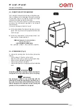
Per  la  salvaguardia  dellʼambiente, 

procedere secondo la normativa lo-

cale vigente.

Quando  lʼapparecchio  non  è  più 

utilizzabile nè riparabile, procedere 

allo smaltimento differenziato dei 

componenti.

Lʼapparecchiatura elettrica non può essere smaltita 

come un rifiuto urbano, ma è necessario rispettare 

la raccolta separata introdotta dalla disciplina spe-

ciale per lo smaltimento dei rifiuti derivati da appa

-

recchiature elettriche (d.l. n° 49 del 14/03/2014 per 

l’attuazione delle direttive 2012/19/EU RAEE e d.l. 

n° 27 del 4/03/2014 per l’attuazione delle direttive 

2011/65/EU ROHS).

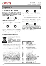
Le apparecchiature elettriche sono contrassegnate 

da un simbolo recante un contenitore di spazzatura 

su ruote barrato. Il simbolo indica che lʼapparecchiat

-

ura è stata immessa sul mercato dopo il 13 agosto 

2005 e che deve essere oggetto di raccolta separata.

Lo smaltimento inadeguato o abusivo delle appa-

recchiature oppure un uso improprio delle stesse, in 

considerazione delle sostanze e dei materiali conte-

nuti può causare danni alle persone e allʼambiente. 

Lo smaltimento dei rifiuti elettrici che non rispetti le 

norme vigenti  comporta lʼapplicazione  di sanzioni 

amministrative e penali.

  ATTENZIONE  

Per  quanto  concerne  lo  smaltimento  di  sostanze 

nocive  (lubrificanti,  solventi,  prodotti  vernicianti, 

etc.) consultare il paragrafo successivo.

7.3 -  SmALTImENTO DELLE SOSTANZE NOCIVE

Per procedere allo smaltimento di dette sostanze con-

sultare quanto prescritto dalle Normative Vigenti nel 

singolo paese ed operare di conseguenza.

  ATTENZIONE  

Qualunque irregolarità commessa dal Cliente prima, 

durante o dopo la rottamazione e lo smaltimento dei 

componenti della macchina,  nellʼinterpretazione ed 

applicazione delle Normative Vigenti in materia, è di 

esclusiva responsabilità dello Stesso.

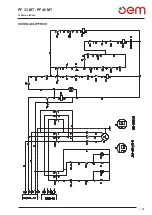
LEGENDA SCHEMA ELETTRICO

KM1: 


Contattore salita

KM2: 


Contattore discesa

KM3:


Relè resistenza piatto inferiore

M: 


Motore elettrico trifase

R1: 


Resistenza piatto inferiore

R2:


Resistenza piatto superiore

SQ1: 


Micro blocco inversione di fase

SQ2: 


Micro superiore

SQ3: 


Micro inferiore

SQ4: 


Micro posizione capote

SQ5: 


Micro posizione capote

SB1: 


Pulsante di marcia

SB2: 


Pulsante di marcia

KT1: 


Temporizzatore 0 - 6 secondi

FR1: 


Termica interna al motore

X2: 


Connettore 15 poli maschio / femmina

M1: 


Motore trifase 0,25 Kw 230/400 V

ST1: 


Termostato resistenza superiore

ST2: 


Termostato resistenza inferiore

ST3: 


Termostato di sicurezza

HL2: 


Lampada spia resistenza sup.

HL3: 


Lampada spia resistenza inf.

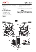
Summary of Contents for PF 33 MT

Page 1: ...ORMER LA PIZZA PRESSFORM PRESSFORM PIZZA FORMMASCHINEN FORMADORAS PARA PIZZA PRESSFORM MODELADORAS PARA PIZZA PRESSFORM MANUALE D USO E LA MANUTENZIONE OPERATING AND SERVICE MANUAL MODE D EMPLOI ET D...

Page 2: ......

Page 3: ...AGENTI OFFICES OR AGENTS Si ges ou Agents NIEDERLASSUNGEN oder VERTRETER SEDES y AGENTES SEDE ou AGENTES COSTRUTTORE MANUFACTURER PRODUCTEUR HERSTELLER FABRICANTE FABRICANTE Modello Numero di matricol...

Page 4: ......

Page 5: ...l legale rappresentante Signature of the legal representative Massimo Giussani DICHIARAZIONE CE DI CONFORMITA DECLARATION OF CONFORMITY DECLARATION CE DE CONFORMITE CE KONFORMIT TSERKL RUNG DECLARACI...

Page 6: ...EICHNIS NDICE GENERAL NDICE GERAL Italiano Pag IT 1 Istruzioni originali English Pag EN 1 Translation of original instructions Fran ais Pag FR 1 Traduction des instructions d origine Deutsch Seite DE...

Page 7: ...3 4 PRIMO AVVIAMENTO Pag I 11 CAPITOLO 4 Capitolo per il tecnico e l operatore 4 1 TIPO DI UTILIZZO E CONTROINDICAZIONI D USO Pag I 12 4 2 TARGHETTE DI SICUREZZA Pag I 12 4 3 SICUREZZE Pag I 15 4 4 ZO...

Page 8: ...regenerale Tutti i controlli e le operazioni di manutenzione che richiedono la rimozione delle protezioni di sicurezza vengono effettuati sotto la completa responsabilit dell utente Siraccomandapertan...

Page 9: ...zza dell operatore INCASODIDUBBIORICHIEDERESEMPREL INT ERVENTO DI PERSONALE SPECIALIZZATO Qualsiasi manomissionE ELETTRICO ELETTRONICO O MECCANICO DELLA MACCHINA da parte dell utente E SE L USO DELLA...

Page 10: ...dalle vigenti norme nazionali del luogo e dotato di una efficiente messa a terra Posizionare sulla linea di alimentazione a monte della macchina un dispositivo onnipolare di sezio namento I cavi elett...

Page 11: ...46 MT 60 85 90 Capitolo 2 misure in cm DIMENSIONI DI INGOMBRO 2 1 CARATTERISTICHE TECNICHE Mod Dim esterne cm LxPxH Diametro massimo cm Kw max Max temp C Peso netto Kg PF 33 MT 41x55x78 33 cm 3 25 400...

Page 12: ...n la massima cura Per eseguire il sollevamento ed il posizionamento della scatola occorre utilizzare appropriati sistemi di sollevamento scelti in funzione al peso della stessa Il sollevamento della s...

Page 13: ...rizzando la corrispondenza a OEM ALI Group S r l a Socio Unico Viale Lombardia 33 46012 BOZZOLO MN Italia Tel 39 0376 910511 Fax 39 0376 920754 2 4 DISIMBALLO Fig 3 Per togliere la macchina dall imbal...

Page 14: ...Cruscotto comandi 5 Piedini di appoggio 6 Regolazione spessore pasta 7 Cavo elettrico di alimentazione 8 Targa dati 9 Supporto carrellato Optional 10 Protezione inferiore 11 Protezione laterale 2 6 ID...

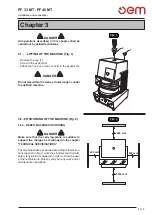
Page 15: ...golfare 2 PERICOLO Non sostare nel raggio di azione della gru o paranco o sotto la macchina sollevata 3 2 POSIZIONAMENTO MACCHINA Fig 2 3 2 a POSIZIONAMENTO MACCHINA A BANCO PERICOLO Assicurarsi che i...

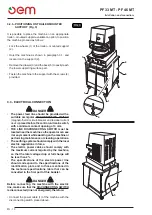
Page 16: ...ima di 3 mm Il SEZIONATORE DI LINEA deve essere collocato in prossimit della macchina in modo tale che il suo stato possa essere visionato in qualsiasi momento dall operatore durante le operazione di...

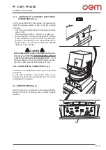
Page 17: ...uindi spegnere immediatamente la macchina posizionando l interruttore 1 su 0 e disinserire l interruttore posto a monte della macchina PERICOLO Prima di effettuare modifiche al collegamento elet trico...

Page 18: ...eriali esplosivi Pressare materiali contenenti alcolici Queste sono solo alcune indicazioni e sono solo a titolo di esempio 4 2 TARGHETTE DI SICUREZZA Fig 1 In tutte le zone pericolose per l operatore...

Page 19: ...are istruzioni Consultare il manuale di istruzioni prima di effettuare l allacciamento elettrico Consultare documentazione annessa Consultare obbligatoriamente la documentazione annessa Il simbolo pos...

Page 20: ...e un dito possa essere introdotto dall alto mentre la capotta abbas sata Organi meccanici in movimento Pericolo organi meccanici in movimento La marcatura organi meccanici in movimento appli cata sul...

Page 21: ...e 3 Capotte o protezione superiore 3 se sollevata du rante la discesa del piatto superiore blocca il piatto nella posizione raggiunta abbassando la capotte protezione il piatto si riposiziona nella po...

Page 22: ...pallina di pasta e togliere age volmente il disco di pasta pressato per le varie posizioni consentite vedi Fig 3 posizioni O consentito al tecnico per le operazioni di manuten zione il posizionamento...

Page 23: ...ra impostata la lampada si spegne 4 Termostato riscaldamento piatto superiore Ruotando la manopola del termostato 4 si imposta la temperatura del piatto superiore 5 Termostato riscaldamento piatto inf...

Page 24: ...ere che i piatti raggiungano la temperatura impostata indicata dallo spegnimento dei led 2 e 3 5 3 FUNZIONAMENTO Fig 2 IMPORTANTE Per una corretta stesura della pasta si consiglia che la stessa sia ad...

Page 25: ...i alla superficie dei piatti I piatti devono essere riscaldati ad una temperatura non inferiore ai 130 C Al di sotto di questa tempe ratura la pasta tende ad incollarsi ai piatti I piatti devono esser...

Page 26: ...tura dei piatti troppo bassa 2 I piatti sono sporchi 3 Pasta particolarmente appiccico sa 1 La temperatura dei piatti troppo alta 2 Il tempo di chiusura dei piatti troppo lungo 1 La distanza tra i pia...

Page 27: ...operazioni che devono essere effettuate con scadenza fissa per garantire il corretto funziona mento della macchina 6 1 b INTERVENTI DI MANUTENZIONE ORDINA RIA 6 1 b a Pulizia macchina Fig 1 La pulizia...

Page 28: ...este operazioni devono essere effettuate da personale tecnico specializzato con la macchina fredda e l alimentazione elettrica disinserita nel caso l alimentazione elettrica deve essere inserita proce...

Page 29: ...del termostato stesso termostato 4 resistenza piatto superiore termostato 5 resistenza piatto inferiore 6 1 d c Eliminazione giochi di usura Fig 5 Coniltempo possibilecheilpignone 1 elacremagliera 2 s...

Page 30: ...apparecchiat ura stata immessa sul mercato dopo il 13 agosto 2005 e che deve essere oggetto di raccolta separata Lo smaltimento inadeguato o abusivo delle appa recchiature oppure un uso improprio del...

Page 31: ...PF 33 MT PF 46 MT Schema elettrico I 25 SCHEMA ELETTRICO...

Page 32: ...PF 33 MT PF 46 MT Schema elettrico I 26 SCHEMA ELETTRICO MONOFASE...

Page 33: ...l connection Pag EN 11 3 4 FIRST START Pag EN 11 CHAPTER 4 Chapter for the technician and operator 4 1 TYPE OF USE AND CONTRAINDICATIONS Pag EN 12 4 2 SAFETY PLATES Pag EN 12 4 3 SAFETY DEVICE Pag EN...

Page 34: ...he electrical line Any inspection and maintenance works requir ing the removal of the safety protections are made under the responsibility of the user Therefore it is recommended that the above mentio...

Page 35: ...ELECTRONIC OR MECHANIC TAMPERING OF THE MA CHINE BY THE USER OR IN CASE OF A NEGLIGENT USE OF THE MACHINE THE MANUFACTURER IS RELIEVED FROMANY RESPONSIBILITY AND THE USER WILL BE THE ONLY ONE RESPONS...

Page 36: ...ystem should comply with the local reg ulations and provided with an efficient earthing Place an omnipolar sectioning device on the power feed line above the machine The size of the electric power cab...

Page 37: ...5 84 PF 46 MT 60 85 90 Chapter 2 sizes in cm OVERALL DIMENSIONS 2 1 TECHNICAL FEATURES Mod Outside dim cm LxPxH Max diameter cm Kw max Max temp C Net weight Kg PF 33 MT 41x55x78 33 cm 3 25 400 3N 180...

Page 38: ...the packing Fig 2 The box should be handled with the most care To lift and to position the box use suitable lifting systems according to the weight of the machine The box should be lifted by using a c...

Page 39: ...ad dressing the correspondence to OEM ALI Group S r l a Socio Unico Viale Lombardia 33 46012 BOZZOLO MN Italia Tel 39 0376 910511 Fax 39 0376 920754 2 4 UNPACKING Fig 3 To remove the packing from the...

Page 40: ...upper safety guard 4 Control element board 5 Supporting feet 6 Dough thickness adjustment 7 Electric power supply cable 8 Data plate 9 Trailer mounted support Optional 10 Lower guard 11 Side guard 2 6...

Page 41: ...ot stay within the crane or hoist range or under the uplifted machine 3 2 POSITIONING OF THE MACHINE Fig 2 3 2 a BENCH MACHINE POSITIONING DANGER Make sure that the carrying plane is suitable to suppo...

Page 42: ...ontrol unit main switch with a minimum contact opening of 3 mm THE LINE DISCONNECTING SWITCH must be located near the machine so the operator can see it at any moment while working on the machine or p...

Page 43: ...refore immediately turn off the machine by set tingthe switch 1 to 0 and turn offthe switch located upstream of the machine DANGER Before making any change in the electrical connec tion make sure that...

Page 44: ...ive materials Pressing materials containing alcoholic drinks The above are only some indications by way of example 4 2 SAFETY PLATES Fig 1 The warning plates with explanatory symbols are to be found i...

Page 45: ...Refer to the instructions Refer to the instruction manual before making the electric connection Refer to the attached documentation Reference to the attached documentation is manda tory The symbol is...

Page 46: ...e risk that a finger could be inserted from above while the cover is low ered Moving mechanical parts Hazard of moving mechanical parts The marking moving mechanical parts is applied on the electric p...

Page 47: ...the upper rest position 3 Top or upper guard 3 if raised during descent of the upper dish it locks the dish in the position it has reached lowering the top guard the dish goes back up to the upper re...

Page 48: ...sert the dough ball in the machine as well as easily remove the pressed dough disc from the machine concerning allowed positions see Fig 3 Positions O For maintenance operations the user may put himse...

Page 49: ...temperature has been reached the light goes off 4 Upper dish heating thermostat Turn the thermostat knob 4 to set the upper dish temperature 5 Lower dish heating thermostat Turn the thermostat knob 5...

Page 50: ...Wait for the dishes to reach the set temperature indi cated by the LEDs 2 and 3 going off 5 3 MACHINE FUNCTIONING Fig 2 IMPORTANT For the dough to spread out properly it should be at a minimum temper...

Page 51: ...se The dishes shall be warmed up at a temperature being not lower than 130 C Under this temperature value the dough tends to stick to the dishes The dishes shall be warmed up at a temperature not exce...

Page 52: ...ously 1 The temperature of the dishes is too low 2 The dishes are dirty 3 The dough is particularly sticky 1 The temperature of the dishes is too high 2 The closing time of the dishes is too long 1 Th...

Page 53: ...ance works to be made according to a maintenance plan in order to ensure a correct working of the machine 6 1 b Routine maintenance 6 1 b a Cleaning machine Fig 1 Before starting any work shift the ma...

Page 54: ...EDED DANGER These operations must be carried out by special ized technical staff with the machine cold and the power cut if the power needs to be on operate with extreme care 6 1 d a Checking parallel...

Page 55: ...n the centre of the thermostat upper dish heating element thermostat 4 lower dish heating element thermostat 5 6 1 d c Eliminating play from wear Fig 5 The pinion 1 and the rack 2 may wear over time a...

Page 56: ...that the equipment was sold on the market after August 13 2005 and must be disposed of accordingly Due to the substances and materials it contains inappropriate or illegal disposal of this equipment...

Page 57: ...PF 33 MT PF 46 MT Wiring diagram EN 25 WIRING DIAGRAM...

Page 58: ...PF 33 MT PF 46 MT Wiring diagram EN 26 SINGLE PHASE WIRING DIAGRAM...

Page 59: ...F 11 CHAPITRE 4 Chapitre destin e au technicien et l op rateur 4 1 TYPE D EMPLOI ET CONTRE INDICATIONS Pag F 12 4 2 PLAQUETTES DE SECURITE Pag F 12 4 3 SECURITE Pag F 15 4 4 ZONE OPERATEUR Pag F 16 4...

Page 60: ...nch Tout contr le et op ration d entretien qui rend n cessairel enl vementdesprotectionsdes curit est fait sous la responsabilit de l utilisateur Il est donc tr s important de faire effectuer dites op...

Page 61: ...DEMANDER TOUJOURS L INTERVENTIONDEPERSONNELSPECIALISE TOUTE MODIFICATION ELECTRIQUE ELEC TRONIQUE OU MECANIQUE DE LA MACHINE dE LA part de l utILISATEUR ET TOUT EMPLOI DE LA MACHINEAVEC NEGLIGENCE SO...

Page 62: ...eu d installation et pourvu d une mise la terre efficace Positionner un dispositif omni polaire de section nement sur la ligne d alimentation dans la partie sup rieure de la machine Les c bles lectriq...

Page 63: ...84 PF 46 MT 60 85 90 Chapitre 2 mesure en cm DIMENSIONS 2 1 CARACTERISTIQUES TECHNIQUES Mod Dim ext rieures cm LxPxH Max diam tre cm Kw max Max temp C Poids net Kg PF 33 MT 41x55x78 33 cm 3 25 400 3N...

Page 64: ...attentivement Pour soulever et positionner de la bo te il est n cessaire d u tiliser de syst mes de soul vement convenables choisis d apr s le poids de la bo te Le soul vement de la bo te doit tre fa...

Page 65: ...OEM ALI Group S r l a Socio Unico Viale Lombardia 33 46012 BOZZOLO MN Italia Tel 39 0376 910511 Fax 39 0376 920754 2 4 DESEMBALLAGE Fig 3 Pour enlever la machine da l emballage faire ce qui suit Coup...

Page 66: ...s commandes 5 Pieds d appui 6 R glage de l paisseur de la p te 7 C ble lectrique d alimentation 8 Plaquette de donn es 9 Support chariot Optionnel 10 Protection inf rieure 11 Protection lat rale 2 6 I...

Page 67: ...tionner dans le rayon d action de la grue ou du palan ou au dessous la machine soulev e 3 2 POSITIONNEMENT DE LA MACHINE Fig 2 3 2 a POSITIONNEMENT DE LA MACHINE SUR LE BANC DANGER S assurer que le pl...

Page 68: ...vec ouverture des contactes de 3 mm minimum Le SECTIONNEUR DE LIGNE doit tre plac pr s de la machine de fa on ce que son statut soit visible tout moment pour l op rateur pendant la production la maint...

Page 69: ...que 2 s abaisse par cons quent teindre imm diatement la machine en mettant l interrupteur 1 sur 0 et d sactiver l interrupteur situ en amont de la machine DANGER Avant d effectuer de changements au br...

Page 70: ...Presser des mati res contenant de l alcool Ce ne sont l que quelques indications fournies uniquement titre d exemple 4 2 PLAQUETTES DE SECURITE Fig 1 Dans toutes les zones dangereuses pour l op rateu...

Page 71: ...ulter les instructions Consulter le manuel d instructions avant de commen cer le branchement lectrique Consulter la documentation annexe Consulter obligatoirement la documentation annexe Le symbole es...

Page 72: ...rateur pourrait introduire un doigt en haut de la machine alors qu on abaisse le capot Organes m caniques en mouvement Danger organes m caniques en mouvement Le marquage organes m caniques en mouveme...

Page 73: ...rotection sup rieure 3 est soulev e durant la descente du plaque sup rieur celui ci se bloque dans la position atteinte lorsqu une capot ou une protection est abaiss e le plaque re tourne en position...

Page 74: ...e p te et d enlever facilement le disque de p te press pour les diff rentes positions permises voir Fig 3 positions O Pour toute op ration d entretien il est permis au tech nicien de se positionner da...

Page 75: ...tat pour le chauffage du plaque sup rieur Tourner le bouton du thermostat 4 pour r gler la temp rature du plaque sup rieur 5 Thermostat pour le chauffage du plaque inf rieur Tourner le bouton du therm...

Page 76: ...nent la temp rature s lectionn e ce qui est signal par l extinction des LED 2 et 3 5 3 FONCTIONNEMENT Fig 2 IMPORTANT Pour un talement correct de la p te il est recom mand qu elle soit une temp rature...

Page 77: ...te tend attacher la surface des plaques Les plaques doivent tre chauff s une temp rature inf rieure 130 C Au dessous de cette temp rature la p te tend se coller aux plaques Les plaques doivent tre cha...

Page 78: ...Les plaques sont sales 3 P te particuli rement collante 1 La temp rature des plaques est trop lev e 2 Le temps de fermeture des plaques est trop long 1 La distance entre les plaques n est pas correcte...

Page 79: ...pour assurer un fonc tionnement correcte de la machine 6 1 b INTERVENTIONS D ENTRETIEN ORDI NAIRE 6 1 b a Nettoyage de la machine Fig 1 Le nettoyage de la machine doit tre effectu au d but de chaque r...

Page 80: ...s op rations doivent tre effectu es par des techniciens sp cialis s avec la machine froide et l alimentation lectrique coup e au cas o il serait n cessaire de brancher l alimentation lectrique proc de...

Page 81: ...proprement dit le thermostat 4 correspond la r sistance du plaque sup rieur le thermostat 5 celle du plaque inf rieur 6 1 d c limination des jeux dus l usure Fig 5 la longue il est possible que le pig...

Page 82: ...l doit faire l objet de ramassage s par L coulement inad quat ou abusif des appareillages ou encore une utilisation impropre de ces derniers si l on consid re les substances et mat riaux contenus dans...

Page 83: ...PF 33 MT PF 46 MT F 25 Schema eletrique SCHEMA ELETRIQUE...

Page 84: ...PF 33 MT PF 46 MT F 26 Schema eletrique SCH MA LECTRIQUE MONOPHAS...

Page 85: ...NITT 4 Abschnitt f r Fachtechniker und Benutzer 4 1 BENUTZUNG UND GEBRAUCHSGEGENANZEIGEN Pag D 12 4 2 SICHERHEITSSCHILDER Pag D 12 4 3 SICHERHEITSVORRICHTUNGEN Pag D 15 4 4 BENUTZERFL CHEN Pag D 16 4...

Page 86: ...er oder neben demselben verfahren ist die Spannung der Leitung an der der Hauptschalter ange schlossen ist auszuschalten BeiNachpr fungenundInstandhaltungsverfahren bei denen die Schutz sowie Sicherhe...

Page 87: ...icherheitsumst nde des Benutzers beeintr chtigen k nnten IM ZWEIFELSFALLE IST FACHPERSONAL ZU KONTAKTIEREN BEI AUFBRECHEN DER MASCHINE IM ELEKTRISCHEN ELEKTRONISCHEN ODER MECHANISCHEN BEREICH SOWIE BE...

Page 88: ...lage soll den geltenden Normen des Bestimmungslands entsprechen sowie mit einer angemessenen Erdungsanlage versehen werden An der Zuf hrungsleitung an der oberen Seite der Maschine ist eine allpolige...

Page 89: ...84 PF 46 MT 60 85 90 Abschnitt 2 Masse in cm AUSSENMASSE 2 1 TECHNISCHE MERKMALE Mod Au enmasse cm LxPxH Gr ter Durch messer cm Kw max Max temp C Netto Gewicht Kg PF 33 MT 41x55x78 33 cm 3 25 400 3N 1...

Page 90: ...f ltig erfolgen Zur Durchf hrung der Hebe sowie Positionier verfahren der Schachtel sind f r das Gewicht derselben geeignete Hebemittel auszuw hlen Die Schachtel ist mit Kran oder Flaschenzug mit ge e...

Page 91: ...formieren dabei die Korrespondenz an folgende Adresse richten OEM ALI Group S r l a Socio Unico Viale Lombardia 33 46012 BOZZOLO MN Italia Tel 39 0376 910511 Fax 39 0376 920754 zu senden ist 2 4 AUSPA...

Page 92: ...hutz PF 46 MT 4 Schaltbrett 5 St tzf sse 6 Einstellung Teigst rke 7 Elektrisches Speisekabel 8 Datenschild 9 Verfahrbare Grundfl che Extra 10 Unterer Schutz 11 Seitlicher Schutz 2 6 IDENTIFIKATION DER...

Page 93: ...GEFAHR Es ist verboten neben dem Kran Flaschenzug oder unter der erhobenen Maschine zu stehen 3 2 MASCHINENPOSITIONIEREN Abb 2 3 2 a POSITIONIEREN DER BANK MASCHINE GEFAHRLAGE Sich versichern da die A...

Page 94: ...Steuereinheit mit Mindest ffnung der Kontaktst cke mm 3 anzubringen ist Der LINIENTRENNSCHALTER muss in der N he des Ger tes liegen damit sein Zustand jederzeit vom Bediener w hrend der Arbeit Wartung...

Page 95: ...Schalter vor der Maschine abschalten um die Maschine sofort abzuschalten GEFAHRLAGE Sich vor eventuellen Ver nderungen des elektri schenAnschlusses versichern da der LEITUNGS TRENNSCHALTER ausgeschal...

Page 96: ...alien Pressen von explosionsgef hrlichen Materialien Pressen von alkoholhaltigen Materialien Das sind nur einige Angaben die nur zum Beispiel dienen 4 2 SICHERHEITSSCHILDER Abb 1 Bei allen f r Benutze...

Page 97: ...der Schutzhaube Anleitungen lesen Die Betriebsanleitung durchlesen bevor man den Strom anschlie t Dazugeh rige Dokumentation lesen Unbedingt die dazugeh rige Dokumentation lesen Das Symbol liegt fron...

Page 98: ...hin dass ein Finger von oben eingef hrt w hrend die Haube gesenkt wird in Gefahr ist Mechanische Organe in Bewegung Gefahr mechanische Organe in Bewegung Die Markierung mechanische Organe in Bewegung...

Page 99: ...auben oder oberer Schutz 3 werden diese w h rend der Senkung des oberen Tellers angehoben wird der Teller in der erreichten Position blockiert Wird die Haube der Schutz gesenkt positioniert sich der T...

Page 100: ...problemlos einsetzen bzw die gepresste Teigscheibe leicht entfernen kann m gliche Positionen siehe Fig 3 Positionen O Zur Durchf hrung der Instandhaltungsverfahren darf sich der Benutzer an die hinter...

Page 101: ...aus 4 Thermostat Heizung oberer Teller Durch Drehen des Drehknopfs des Thermostats 4 wird die Temperatur des oberen Tellers eingestellt 5 Thermostat Heizung unterer Teller Durch Drehen des Drehknopfs...

Page 102: ...Abwarten bis die Teller die eingestellte Temperatur erreichen was durch das Erl schen der Leds 2 und 3 angezeigt wird 5 3 MASCHINENBETRIEB Fig 2 WICHTIG F r eine korrekte Ausrollung des Teigs sollte d...

Page 103: ...bei k nnte der Teig an der Tellerfl che haften Die Teller sind bei einer Temperatur die 130 C nicht unterschreiten soll zu erw rmen Unter solchem Temperaturwert k nnte der Teig an den Tellern haften D...

Page 104: ...Die Temperatur der Teller ist zu niedrig 2 Die Teller sind schmutzig 3 Der Teig ist besonders klebrig 1 Die Temperatur der Teller ist zu hoch 2 Die Schliesszeit der Teller ist zu lang 1 Unrichtiger Ab...

Page 105: ...hrleistung eines einwandfreien Betriebs der Maschine in regel m ssigen Abst nden durchzuf hren sind 6 1 b ORDENTLICHE INSTANDHALTUNG 6 1 b a Maschinenreinigung Fig 1 Die Reinigung der Maschine ist vo...

Page 106: ...WENDIGKEIT GEFAHR Diese T tigkeiten m ssen von Fachtechnikern auf der kalten Maschine und bei abgetrennter Strom versorgung ausgef hrt werden Wenn die Strom versorgung eingeschaltet werden muss ist g...

Page 107: ...nd des oberen Tellers Thermostat 5 f r den Heizwiderstand des unteren Tellers 6 1 d c Beseitigung der Verschlei spiele Abb 5 Mit der Zeit k nnten sich das Ritzel 1 und die Zahn stange 2 abnutzen und d...

Page 108: ...ndustrieabfall gesondert entsorgt werden mu Eine unangemessene oder nicht den gesetzlichen Vorschriften entsprechende Entsorgung von elekt rischen Ger ten sowie ein unsachgem er Einsatz kann aufgrund...

Page 109: ...PF 33 MT PF 46 MT D 25 Elektrischer schaltplan Elektrischer schaltplan...

Page 110: ...PF 33 MT PF 46 MT D 26 Elektrischer schaltplan SCHALTPLAN MONOPHASE...

Page 111: ...QUE Pag E 11 CAP TULO 4 Cap tulo para el t cnico y el operador 4 1 TIPO DE EMPLEO Y USOS INADECUADOS Pag E 12 4 2 CHAPAS DE SEGURIDAD Pag E 12 4 3 DISPOSITIVOS DE SEGURIDAD Pag E 15 4 4 ZONAS DEL OPER...

Page 112: ...do el interruptor general Todos los controles y las operaciones de man tenimiento que requieren la eliminaci n de las protecciones tienen que ser efectuados bajo la absoluta responsabilidad del usuari...

Page 113: ...del operador SITIENEDUDASREQUIERASIEMPRELAINTER VENCI N DEL PERSONAL ESPECIALIZADO CualQUIERDA O EL CTRICO ELECTR NICO OMEC NICODELAM quINACAUSADOPOREL USUARIO AS COMO UN USO NEGLIGENTE DE LAMISMA EX...

Page 114: ...les vigentes en el lugar de utilizaci n y estar dotada de una eficiente puesta a tierra Posicione en la l nea de alimentaci n antes de la m quina un dispositivo omnipolar de corte Los cables el ctrico...

Page 115: ...4 PF 46 MT 60 85 90 Cap tulo 2 medidas en cm ESPACIO OCUPADO 2 1 CARACTER STICAS T CNICAS Mod Dim externas cm LxPxH Di metro m ximo cm Kw m x M x temp C Peso neto Kg PF 33 MT 41x55x78 33 cm 3 25 400 3...

Page 116: ...con el m ximo cui dado Para levantar y posicionar la caja hay que utilizar sistemas apropiados para su elevaci n escogidos en funci n del peso de la misma Se debe levantar por medio de una gr a o un...

Page 117: ...respondencia a OEM ALI Group S r l a Socio Unico Viale Lombardia 33 46012 BOZZOLO MN Italia Tel 39 0376 910511 Fax 39 0376 920754 2 4 DESEMBALAJE Fig 3 Para quitar la m quina del embalaje efect e las...

Page 118: ...d PF 46 MT 4 Panel de mandos 5 Patas de apoyo 6 Regulaci n del espesor pasta 7 Cable el ctrico de alimentaci n 8 Chapa de datos 9 Soporte con ruedas Opcional 10 Protecci n inferior 11 Protecci n later...

Page 119: ...ca en el radio de acci n de la gr a o polipasto o debajo de la m quina levantada 3 2 POSICIONAMIENTO DE LA M QUINA Fig 2 3 2 a POSICIONAMIENTO de LA M quina so bre la mesa de trabajo PELIGRO Aseg rese...

Page 120: ...m nima de 3 mm El SECCIONADOR DE L NEA debe colocarse cerca de la m quina de modo tal que su estado pueda ser visto en cualquier momento por el operador durante las operaciones de trabajo mantenimient...

Page 121: ...quina colocan do el interruptor 1 en 0 y desactivar el interruptor colocado por delante de la m quina PELIGRO Antes de efectuar modificaciones en la conexi n el ctrica aseg rese de que el SECCIONADOR...

Page 122: ...rensar materiales que contienen alcoh licos Estas son solo algunas indicaciones y son mera mente a t tuo de ejemplo 4 2 CHAPAS DE SEGURIDAD Fig 1 En todas las zonas peligrosas para el operador o para...

Page 123: ...n Consulte las instrucciones Consulte el manual de instrucciones antes de realizar la conexi n el ctrica Consulte la documentaci n adjunta Consultar obligatoriamente la documentaci n anexa El s mbolo...

Page 124: ...dedo pueda ser introducido desde arriba mientras el cap est bajado rganos mec nicos en movimiento Peligro por rganos mec nicos en movimiento La marca rganos mec nicos en movimiento se aplica en el pa...

Page 125: ...sici n de reposo superior 3 Capotas o protecci n superior 3 si se alza durante el descenso del plato superior bloquea el plato en la posici n alcanzada bajando la capota protecci n el plato se reposic...

Page 126: ...ntrodu cir la bola de masa y quitar f cilmente el disco prensado v ase Fig 3 posiciones permitidas O El t cnico para efectuar las operaciones de mante nimiento puede posicionarse en la parte trasera d...

Page 127: ...a la l mpara se apaga 4 Termostato de calentamiento del plato superior Girando el pomo del termostato 4 se configura la temperatura del plato superior 5 Termostato de calentamiento del plato inferior...

Page 128: ...dor 7 Esperar a que los platos alcancen la temperatura configurada indicada por el apagado de los leds 2 y 3 5 3 FUNCIONAMIENTO Fig 2 IMPORTANTE Para extender correctamente la masa se aconseja que sta...

Page 129: ...caso la masa tiende a pegarse en la superficie de los platos Los platos tienen que calentarse a una temperatura no inferior a los 130 C Por debajo de esta tempera tura la masa tiende a pegarse de los...

Page 130: ...ja 2 Los platos est n sucios 3 Masa muy pegajosa 1 La temperatura de los platos es demasiado alta 2 El tiempo de cierre de los platos es demasiado largo 1 La distancia entre los platos no es correcta...

Page 131: ...ciones que tienen que ser efectuadas dentro de un plazo fijo para garantizar un funcionamiento correcto de la m quina 6 1 b INTERVENCIONES DE MANTENIMIENTO ORDINARIO 6 1 b a Limpieza de la m quina Fig...

Page 132: ...ENIMIENTO SEG N LA NECESIDAD PELIGRO Estas operaciones deben ser efectuadas por per sonal t cnico especializado con la m quina fr a y la alimentaci n el ctrica desactivada en caso que se deba alimenta...

Page 133: ...tato 4 resistencia del plato superior termostato 5 resistencia del plato inferior 6 1 d c Eliminaci n de los juegos de desgaste Fig 5 Con el tiempo es posible que el pi n 1 y la cremallera 2 se consum...

Page 134: ...uedas cruzado por una barra El s mbolo indica que el aparato fue introducido en el mercado despu s del 13 de agosto de 2005 y que debe ser objeto de recogida selectiva de residuos La eliminaci n inade...

Page 135: ...PF 33 MT PF 46 MT Esquema electrico E 25 ESQUEMA ELECTRICO...

Page 136: ...PF 33 MT PF 46 MT Esquema electrico E 26 ESQUEMA EL CTRICO MONOF SICO...

Page 137: ...4 Cap tulo destinado ao t cnico e ao operador 4 1 TIPO DI USO E CONTRA INDICA ES DE USO Pag P 12 4 2 PLACAS DE SEGURAN A Pag P 12 4 3 DISPOSITIVOS DE SEGURAN A Pag P 15 4 4 ZONAS OPERADOR Pag P 16 4 5...

Page 138: ...tor geral Todososcontroloseasopera esdemanuten o que requerem a remo o das protec es de seguran a s o efectuados sob a completa responsabilidade do usu rio Portanto aconselh vel que tais opera es seja...

Page 139: ...do operador NOCASODED VIDAS SOLICITARAINTER VEN O DE PESSOAL ESPECIALIZADO QuaLqueraltera o EL CTRICa ELEc TRONICa Ou MEC NICa feita na M quINA pelo usu rio E SE o USO DA M quINA for feitO COm NEGLIG...

Page 140: ...mas nacionais locais em vigor e dotada de instala o terra eficiente Posicionar na linha de alimenta o antes da m qui na um dispositivo omnipolar de seccionamento Os cabos el ctricos de alimenta o deve...

Page 141: ...PF 46 MT 60 85 90 Cap tulo 2 medidas em cm DIMENS ES DE VOLUME 2 1 CARACTERISTICAS T CNICAS Mod Dim externas cm LxPxH Di metro m ximo cm Kw m x M x temp C Peso neto Kg PF 33 MT 41x55x78 33 cm 3 25 400...

Page 142: ...o cuidado Para efectuar o levantamento e o posicionamento da caixa preciso utilizar sistemas de levantamento apro priados escolhidos em fun o do peso da mesma O levantamento da caixa deve ser efectuad...

Page 143: ...acimaespecificadoenviandoacorrespond nciapara OEM ALI Group S r l a Socio Unico Viale Lombardia 33 46012 BOZZOLO MN Italia Tel 39 0376 910511 Fax 39 0376 920754 2 4 DESEMBALAGEM Fig 3 Para desembalar...

Page 144: ...ran a PF 46 MT 4 Pain l controlos 5 P zinhos de apoio 6 Regula o da espessura da massa 7 Cabo el ctrico de alimenta o 8 Placa dados 9 Suporte com carrinho rodinhas Opcional 10 Protec o inferior 11 Pro...

Page 145: ...do raio de ac o do guindaste ou roldana e n o se posicionar debaixo da m quina levantada 3 2 POSICIONAMENTO M QUINA Fig 2 3 2 a POSICIONAMENTO M QUINA NO SUPOR TE PERIGO Assegurar se que o plano de ap...

Page 146: ...eral da unidade de controlo com abertura m nima dos contactos de 3 mm O INTERRUPTOR DE ALIMENTA O deve ser colocado pr ximo da m quina por forma a ser sempre vis vel em qualquer momento pelo ope rador...

Page 147: ...ixa em seguida desligar imediatamente a m quina posicionando o interruptor 1 em 0 e desactivar o interruptor localizado a montante da m quina PERIGO Antes de efectuar modifica es na liga o el ctri ca...

Page 148: ...Prensar materiais explosivos Prensar materiais que contenham lcool Estas s o apenas algumas das indica es e s o fornecidas a t tulo de exemplo 4 2 PLACAS DE SEGURAN A Fig 1 Em todas as reas perigosas...

Page 149: ...nsultar as instru es Consultar o manual de instru es antes de realizar a liga o el ctrica Consultar a documenta o em anexo Consultar obrigatoriamente a documenta o em ane xo O s mbolo deve ser colocad...

Page 150: ...to de um dedo ser introduzido a partir da parte superior com a tampa retirada Pe as mec nicas em movimento Perigo de pe as mec nicas em movimento A marca o pe as mec nicas em movimento deve ser coloca...

Page 151: ...para a posi o de repouso superior 3 Cobertura ou protec o superior 3 se for levantada durante a descida do prato superior bloqueia o prato na posi o alcan ada baixando a cobertura protec o o prato ret...

Page 152: ...facilmente a bolinha de massa e extrair com facilidade o disco de massa prensado para as v rias posi es consentidas ver Fig 3 posi es O permitido ao t cnico se posicionar na parte posterior da m quina...

Page 153: ...ngida a l mpada apaga se 4 Term stato de aquecimento do prato superior Rodando o man pulo do term stato 4 define se a temperatura do prato superior 5 Term stato de aquecimento do prato inferior Rodand...

Page 154: ...ardar que os pratos atinjam a temperatura defini da indicada pelo apagamento dos LED 2 e 3 5 3 FUNCIONAMENTO Fig 2 IMPORTANTE Para que a massa fique bem confeccionada reco menda se que a mesma esteja...

Page 155: ...caso a massa tende a grudar na superf cie dos pratos Os pratos devem ser aquecidos a uma temperatura n o inferior aos 130 C Abaixo dessa temperatura a massa tende a grudar nos pratos Os pratos devem s...

Page 156: ...pratos muito baixa 2 Os pratos est o sujos 3 Massa particularmente grudenta 1 Atemperatura dos pratos muito alta 2 O tempo e fechamento dos pra tos muito demorado 1 A dist ncia entre os pratos n o est...

Page 157: ...a es que devem ser efec tuadas com prazo fixo para garantir um correcto funcionamento da m quina 6 1 b OPERA ES DE MANUTEN O ORDIN RIA 6 1 b a Limpeza da m quina Fig 1 A limpeza da m quina deve ser ef...

Page 158: ...ECESS RIO PERIGO Estas opera es devem ser efectuadas por pes soal t cnico especializado com a m quina fria e a alimenta o el ctrica desligada Se for necess rio ligar a alimenta o el ctrica proceder co...

Page 159: ...m stato 4 da resist ncia do prato superior term stato 5 da resist ncia do prato inferior 6 1 d c Elimina o de folgas provocadas por desgaste Fig 5 Com o passar do tempo o pinh o 1 e a cremalheira 2 po...

Page 160: ...2005 e ter que ser objecto de recolha separada A elimina o inadequada ou abusiva dos equipamen tos ou um uso impr prio dos mesmos em conside ra o das subst ncias e dos materiais contidos pode causar...

Page 161: ...PF 33 MT PF 46 MT Esquema el ctricos P 25 ESQUEMA EL CTRICOS...

Page 162: ...PF 33 MT PF 46 MT Esquema el ctricos E 26 ESQUEMA EL CTRICO MONOF SICO...

Page 163: ......

Page 164: ...Cod OMMIPF000 Rev 02 del 04 2019 OEM ALI Group S r l a Socio Unico Viale Lombardia 33 46012 BOZZOLO MN Italia Tel 39 0376 910511 Fax 39 0376 920754...

Reviews: