


EMBEDDED
PLC BL2500 User’s Manual
Running Sample Applications
OEM Technology Solutions
Page 34
11. Select the
Insert a Repeat-Until
button
and place it in between the “Begin” symbol and the
“SW1 = SW2” test symbol. Press Delete to just leave the flow line connector behind
.
12. Select the
flow link
between the “Begin” symbol and the “End” symbol and delete it to allow for the
program to run continuously without ending.
13. Click on the flow line connector that both the “LED_OFF” and the “LED_ON” action symbols connect
to. Select the
Insert a flow
button
and connect both the “LED_OFF” and the “LED_ON” action
symbols to the flow line connector remaining from
Step 11.
This allows the “SW1 = SW2” test to
repeat continuously, so if either of SW1 or SW2 change it can test again and change the LED1
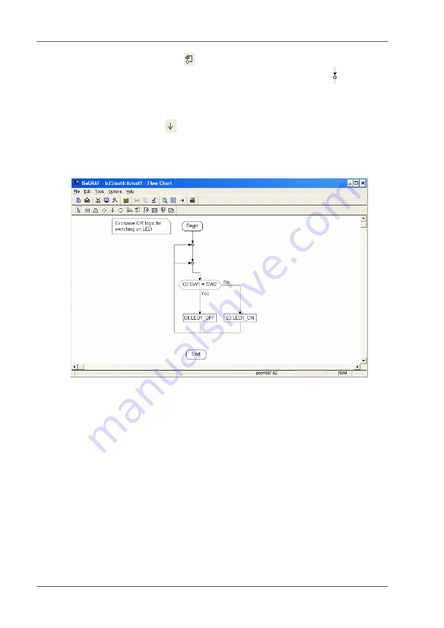
output.
14. The
FCtest1 Flow Chart
should now appear as follows:
15. Save the program by selecting
File
menu
→
Save
. Press
OK
button on the
Update diary
window.
Close the
FCtest1 – Flow Chart
window.
16. Follow Steps 17 to 25 in 3.4.1 to compile and download it to the Target PLC.
17. Double-click on
FCtest1
program. The
FCTEST1 – Flow Chart
window is displayed. Short circuit the
digital input IN00 (SW1 will be FALSE), the LED1 will be turned ON as well as the state of LED1 in
the Programs window will change. The PLC program implements a Boolean XOR operation on SW1
and SW2 with the result set on the LED1.
18. To stop the monitoring of the PLC application, close the
Debugger
window. The programs and
dictionary windows in debug mode will be closed.
The ISaGRAF User’s Manual (See [2]) and the on-line help of the ISaGRAF Workbench describes in
detail all the Workbench functionalities (editor, simulation, debugger, etc.) including also a reference
manual of the PLC programming languages (IEC 61131-3).