9600 Periodic Maintenance Procedure
00-880606-02
Page 11
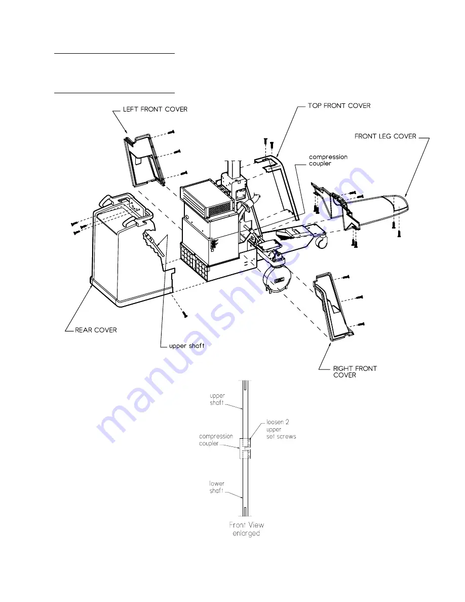
Removing the Mobile C-Arm
covers, newer system with center
pivot steering
Page 1: ...e 00 880606 02 GE OEC Medical Systems Inc Rev C 9600 Standard system left front view 9600 Standard system right rear view 9600 Super C system left front view 9600 Super C system right rear view 9600 W...
Page 2: ...at any time be incorporated in the hardware and software and may not be reflected in this version of the document Contact OEC Technical Support for clarification if discrepancies arise CAUTION Federal...
Page 3: ...atic Drag Wire 18 1 2 ELECTRICAL INSPECTIONS 18 GROUND CONTINUITY 18 ELECTRICAL PLUG POWER CORD 19 INTERCONNECT CABLE and PINS 19 MOTORIZED FUNCTIONS LIMIT SWITCHES 19 TECHNIQUE DISPLAY 20 CONTROL PAN...
Page 4: ...SUBTRACTION OPTION 30 ZOOM OPTION 31 SHARPEN OPTION 31 DIGITAL FLUOROGRAPHY PULSE 31 CARDIAC OPTION 31 LAST IMAGE HOLD 32 COOLING FAN OPTION 32 SYSTEM ACCESSORIES TESTED 33 VTR OPTION 33 THERMAL PRIN...
Page 5: ...version of the manual is accurate at the time of the manual s release however product changes and improvements can occur at any time and may not be reflected here This document distinguishes differen...
Page 6: ...taking X rays the high voltage cables can retain a lethal charge even if you power down the system High voltages can arc several inches from their terminals if the cables are removed from the connecto...
Page 7: ...y be found on the system X RAY SAFETY WARNING ELECTRICAL SAFETY WARNING WARNING SYMBOLS The following symbols may be found on the Mobile C Arm DANGEROUS VOLTAGE PRESENT Dangerous voltages are present...
Page 8: ...and the first electrical connection made during servicing procedures POTENTIAL EQUALIZA TION GRN YEL wire is used to indicate protective earth conductors accessible parts connected to earth parts and...
Page 9: ...NING Electrical circuits inside the equipment use voltages that are capable of causing serious injury or death from electrical shock Use appropriate precautions 1 If the system has power applied turn...
Page 10: ...Refer to 9600 System Service Manual and see the illustration below For newer systems with center pivot steering remove the front leg cover right front cover left front cover and top front cover Then l...
Page 11: ...9600 Periodic Maintenance Procedure 00 880606 02 Page 11 Removing the Mobile C Arm covers newer system with center pivot steering...
Page 12: ...upler to where there is a 1 4 inch to 3 8 inch gap between the ends of the shafts CAUTION Be sure the wheels are positioned forward straight and the set screw heads face directly front when inserted i...
Page 13: ...is engaged and that the Cross Arm will not move The brake handle should tighten the brake with a minimum of travel Excessive movement may indicate brake wear 3 Refer to the Non Motorized Movements Cro...
Page 14: ...at some older systems use the rear lock position for caster locking 2 Select the FREE steering or neutral mode with the pedals in the flat position then push the C Arm while steering it in various dir...
Page 15: ...n perpendicular to the floor lock the C Arm orbital brake unlock the flip flop brake and rotate the C Arm until the C Arm is horizontal with the floor 2 Lock the flip flop brake release the C Arm orbi...
Page 16: ...y inspect a polyurethane stop the Control Panel housing must be removed 4 If brake tension requires adjustment remove the Torx screw securing the brake handle to the brake assembly and then remove the...
Page 17: ...brake shoe should be barely touching the Cross Arm 6 Tighten the 4 torx screws to secure the brake mount to the Cross Arm housing 7 With the handle in the slightly angled position use Loctite 222 and...
Page 18: ...the elapsed time indicator that prevents access to the isolation transformer T1 3 Verify continuity between the following From To Spec Interconnect Cable J1 16 Chassis AC Power Plug Ground Pin 0 5 Int...
Page 19: ...h to ON VERTICAL LIFT 1 Raise the vertical column until the upper limit switch is activated 2 Lower the vertical column until the lower limit switch is activated 3 Verify smooth motor operation 4 Obse...
Page 20: ...then switch it back to ON and verify the operations as listed TECHNIQUE DISPLAY 1 After turning the Workstation keyswitch to ON verify the X ray technique displays on the C Arm control panel CONTROL P...
Page 21: ...nd verify the message INTERLOCKS OPEN is displayed on the C Arm display 2 Press any button on the C Arm control panel to reboot the C Arm The C Arm will reboot 3 Repeat steps 1 and 2 with the second F...
Page 22: ...el display NOTE Eventually the message STATUS V n nn will indicate that you have entered the status mode NOTE Scroll through the choices listed within the menu by pressing either the kVp or mA switche...
Page 23: ...rify the different ABS tables can be selected and loaded 2 POWER SUPPLIES BATTERY INSPECTIONS 2 1 SYSTEM BATTERIES GENERATOR BATTERIES This procedure can be used to verify that a fully charged set of...
Page 24: ...is a busy LED that indicates when the SRAM is being accessed If both LED s illuminate RED during disk access the battery is not charged adequately 1 With the SRAM in the Solid State Disk use a jewele...
Page 25: ...ecautions 3 1 DOSE RATE Entrance exposure is the amount of radiation available at the entrance point of patient anatomy Entrance exposure is measured 12 or 30 cm above the surface of the Image Intensi...
Page 26: ...uracy of the system WARNING The following steps produce X rays Use appropriate precautions FLUORO MODE Set the system to FLUORO MANUAL mode Use a kVp meter or Dynalyzer for the measurements SET KVP FL...
Page 27: ...KV TRACKING NORMAL AUTO MODE 1 Select the STANDARD ABS Table 2 Select AUTO FLUORO technique mode and the NORMAL field size 3 Make exposures with one two and three copper filters added in the beam path...
Page 28: ...free of dust lint or any substance which would inhibit air flow 3 Reconnect the 2 fan wires if disconnected and note their color code black to black red to red then reattach the HV cable cover to the...
Page 29: ...Rotate the camera and observe the indicator arrow as it rotates around the perimeter of the image Discontinue rotation and note where the arrow is pointing toward the image H Make another exposure and...
Page 30: ...the exposure is averaged and integrated and the exposure automatically terminates ROADMAP OPTION Verify proper operation of Roadmap with the following steps 1 Press the ROADMAP key on the front panel...
Page 31: ...ail is enhanced 3 Take another exposure and then press and hold SHARPEN while pressing the trackpad 4 Verify the amount of edge enhancement varies DIGITAL FLUOROGRAPHY PULSE 1 Cover the II with a lead...
Page 32: ...pulse Boost exposure rate is 20 seconds after 20 sec exposure is automatically terminated and BOOST OVERTIME displays on the control panel 14 Maximum mA is 60 mA 15 kV range is 40 120 kV LAST IMAGE HO...
Page 33: ...mera and verify the camera operation JAZ DRIVE OPTION NOTE Refer to the Supplement Removable Cine Storage 00 879857 to aid in testing Jaz drive operation Verify proper operation of the Jaz drive with...
Page 34: ...er to expose the Collimator NOTE Do not over lubricate the Collimator Iris Ring Use Permatex Super Lube P N 88 299483 00 or equivalent 2 Sparingly lubricate the edge of the Collimator Iris Ring that r...
Page 35: ...with Permatex Super Lube Spray P N 88 299485 00 5 X RAY BEAM ALIGNMENT VERIFIED annual pm only WARNING The following steps produce X rays Use appropriate precautions Setup 1 To nominalize C Arm flexu...
Page 36: ...the alignment tool Make the following four exposures on one sheet of film 2 Select Manual Fluoro Normal field and then Film mode Take a 50 kVp 0 9 mAs exposure 3 Select Manual Fluoro MAG 1 field and...
Page 37: ...1 Calculate and record the absolute value of the difference between the film and Workstation Y axis values as follows YN YStep 8 YStep 9 Verify the difference is less than 28 mm 3 SID Write the YN val...
Page 38: ...between the film and Workstation X axis values as follows X2 XStep 18 XStep 19 Verify the difference is less than 28 mm 3 SID Write the X2 value on the form 21 MAG 2 field Calculate and record the abs...
Page 39: ...dition to common hand tools the following tools are required Torx Screwdriver Set Spline Driver 048 P N 00 900920 01 TEST EQUIPMENT Oscilloscope Tektronix 2236 or equivalent Digital Volt Ohm Meter Dos...
Page 40: ...CUP TORQUE SPECIFICATIONS TORX SCREW SIZE NOMINAL TORQUE VALUE ACCEPTABLE RANGE 4 40 6 lbs in 5 8 lbs in 6 32 15 lbs in 13 16 lbs in 8 32 22 lbs in 21 24 lbs in 10 32 30 lbs in 28 31 lbs in LUBRICATIO...