


174
When this parameter is set, the values of the basic gain will change
after referring to the inertia ratio (SEt-66).
•
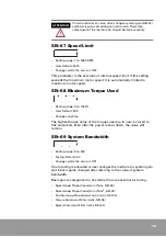
System Gain (SEt-42)
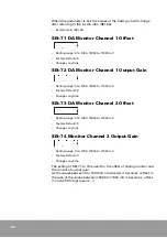
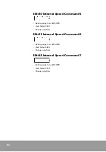
SEt-71 DA Monitor Channel 1 Offset
•
Setting range: 0 to 1000, 10000 to 11000 mV
•
Factory Default: 0
•
Changes anytime
SEt-72 DA Monitor Channel 1 Output Gain
•
Setting range: 0 to 1000, 10000 to 11000 mV
•
Factory Default: 0
•
Changes anytime
SEt-73 DA Monitor Channel 2 Offset
•
Setting range: 0 to 1000, 10000 to 11000 mV
•
Factory Default: 0
•
Changes anytime
SEt-74 Monitor Channel 2 Output Gain
•
Setting range: 0 to 1000, 10000 to 11000 mV
•
Factory Default: 0
•
Changes anytime
The setting of SEt-71 to 74 is used for the offset of analog monitor and
the control of output gain.
As the values between 0 to 1000 mV are entered, it boffset, in
the case of the values between 10000 to 11000 mV, it becomes - offset.
(1 on the fifth digit means ’-’.)
Summary of Contents for CSDP Plus
Page 1: ...Maximum Value for OEMs SM CSDP Plus Servo Drive User Manual...
Page 16: ...18...
Page 30: ...32 Higher Control Connector CN1 Circuit Diagram...
Page 33: ...35 Compact Absolute Encoder Wiring Serial Encoder Wiring...
Page 38: ...40...
Page 120: ...122...
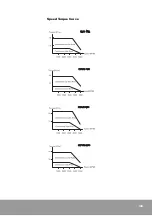
Page 179: ...181 Speed Torque Curve...
Page 180: ...182...
Page 183: ...185 Speed Torque Curve...
Page 184: ...186...
Page 187: ...189...
Page 190: ...192 Speed Torque Curve...
Page 193: ...195...
Page 196: ...198...
Page 201: ...203...
Page 204: ...206...
Page 207: ...209...
Page 210: ...212...
Page 215: ...217...
Page 230: ...232...
Page 252: ...254...
Page 253: ......