background image

1


length 

exceeds 

the 

maximum 

allowable  value  of  125  (Word)  or 
2000  (Bit),  it  needs  to  modify  the 
length 

0x04


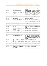
Data processing error 

Check  whether  the  data  value  range 
meets the requirements of the slave 

0x05


Application  layer  length  does 
not match 

Increase  the  receiving  character 
interval 

and 

check 

the 

communication parameter settings 

0x06


Protocol ID error 

Check the sender message 

0x07 

Buffer address error 

Device internal error 

0x08 

Bit offset error 

Device internal error 

0x09 

The slave  ID number does not 
match 

Increase  the  timeout  period,  check 
the  hardware  connection  status,  and 
check  the  communication  parameter 
settings 

0x0A 

CRC check error 

CRC error, check the communication 
line 

0x0B 

LRC error 

LRC error, check the communication 
line 

0x0C 

Response  function  code  does 
not match 

Check hardware connection status 

0x0D 

Response  address  does  not 
match 

Check hardware connection status 

0x0E 

Response  data  length  does  not 
match 

Check hardware connection status 

0x0F 

Communication timeout 

Increase  the  timeout  period,  check 
the  hardware  connection  status,  and 
check  the  communication  parameter 
settings 

0x10 

ASCII  mode  start  character 
error 

„:‟ Colon start character error 

0x11 

ASCII  mode  ending  character 
error 

CR/LF  carriage  return  and  line  feed 
terminator error 

0x12 

ASCII mode non-character 

The  data  contains  non-hexadecimal 
ASCII codes 

0x13 

Wrong number of characters in 
ASCII mode 

Slave response length error 


Summary of Contents for ODOT-S4E2

Page 1: ...1 Modbus RTU ASCII to Modbus TCP Protocol Converter ODOT Series Gateways ODOT S4E2 User Manual ODOT Automation System Co Ltd 2020 09 20 Copyright 2020 All rights reserved by ODOT Automation...

Page 2: ...2 Hardware Updating CCL Ownership information Without the consent of the copyright owner the whole or part of this document do not be republished as paper or electronic document Disclaimer This docume...

Page 3: ...res 4 1 3 Technical parameters 5 2 Hardware description 7 2 1 Product appearance 7 2 2 LED indicator description 7 2 3 Terminal definition 8 2 4 Reset button 10 2 5 External terminal resistance 12 2 6...

Page 4: ...anti reverse connection protection Communication terminal isolation processing 1500V isolation voltage Dual Ethernet port with switch function support cascading 2 kV network port isolation protection...

Page 5: ...ory Settings 35mm standard DIN rail EMC complies EN 55022 2010 EN55024 2010 international standard 1 3 Technical parameters The relevant technical parameters of this product are shown in Table 1 Pleas...

Page 6: ...ber of serial port 4 RS485 RS232 or 2 RS422 Serial Communication mode RTU mode ASCII mode is optional Baud rate 1200 115200 bps Checking mode None odd even Number of slave supported Max 124 without re...

Page 7: ...7 2 Hardware description 2 1 Product appearance 2 2 LED indicator description There are total 6 LED status indicators The symbol definition and status description are shown in Table 2...

Page 8: ...receiving indicator Flashing Series port 2 is sending receiving data ON Series port 2 is not sending receiving data CO3 Series port 3sending receiving indicator Flashing Series port 3 is sending recei...

Page 9: ...ignal Grounded Signal Grounded 8 PE Shield Earthing Shield Earthing Shield Earthing 9 3RT Serial Port3 RS485 Serial Port3 RS232_RX RS422 Channel 2 RS422 Sending Negative Terminal 10 3TT Serial Port3 R...

Page 10: ...e will be restarted Click the reset button with a paper clip and all the indicator lights will shine once to indicate successful reset So the gateway reset is successful The technical parameters of th...

Page 11: ...erial port side Serial port mode Master station mode Protocol type of Modbus Modbus RTU Serial port baud rate 9600bps Check digit No check Data bits 8bit Stop bit 1bit Receive character interval 3 5t...

Page 12: ...characteristic impedance of the transmission cable In short distance transmission no terminating resistor is required that means no terminating resistor is generally required below 300 meters The term...

Page 13: ...bus RTU ASCII master could communicate with one Modbus RTU ASCII slave at the same time 3 1 2 Gateway working mode There are two types of working modes transparent mode and mapping mode and the Transp...

Page 14: ...in total Part 5 System diagnostic DO storage area it stores the station equipment working status 263 points in total And it could access to the system diagnostic area and obtain the slave information...

Page 15: ...responding error indicator bit will have zero clearing automatically after the slave is back to normal Its data encoding format is shown in Table 3 2 Table 3 2 Slave error indicating area encoding for...

Page 16: ...1 Address 0x200F Bit Number x x x x x x x x BIT Bit7 Bit6 Bit5 Bit4 Bit3 Bit2 Bit1 Bit0 Bit Number x 247 246 245 244 243 242 241...

Page 17: ...ng the currently executed function code mapped to the slave Byte0 is the low byte indicating the current error code of the salve communication The specific meaning of the error code of the slave is as...

Page 18: ...n parameter settings 0x0A CRC check error CRC error check the communication line 0x0B LRC error LRC error check the communication line 0x0C Response function code does not match Check hardware connect...

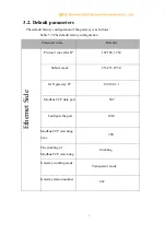
Page 19: ...uration Parameter name Defaults Ethernet Side Protocol converter IP 192 168 1 254 Subnet mask 253 253 253 0 LAN gateway IP 192 168 1 1 Modbus TCP data port 502 Configure the port 1024 Modbus TCP watch...

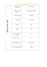
Page 20: ...de Master mode Modbus protocol type Modbus RTU ASCII Serial baud rate 9600bps Check digit No check Data bits 8bit Stop bit 1bit Receive character interval 3 5t Message sent 0 Timeout processing Data r...

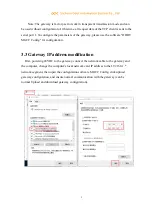
Page 21: ...software ODOT MGCC Config for configuration 3 3 Gateway IP address modification First powering 24VDC to the gateway connect the network cable to the gateway and the computer change the computer s loca...

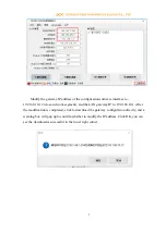
Page 22: ...s network segment and the LAN gateway IP to 192 168 10 1 After the modification is completed click to download the gateway configuration directly and a warning box will pop up to confirm whether to mo...

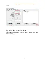
Page 23: ...ed you need to change the computer s IP address to 192 168 10 network segment Click Upload Gateway Configuration on the configuration software MGCC Config interface After the upload is successful you...

Page 24: ...2 corner 3 4 Typical application description 3 4 1 Realize communication between Modbus TCP client and Modbus RTU ASCII slave...

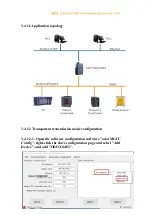
Page 25: ...ation topology 3 4 1 2 Transparent transmission mode configuration 3 4 1 2 1 Open the software configuration software odot MGCC Config right click the slave configuration page and select Add Device an...

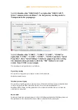
Page 26: ...aning of each parameter is as follows Operating mode It is used to set up gateway as master or slave in the network Default is master mode Modbus protocol type It is used to set up the gateway s proto...

Page 27: ...me of a single character and it is related with baud rate In general there is no need to change this parameter Packet transmission interval Interval time for sending Modbus commands Delayed time from...

Page 28: ...Confirm to return The station number of the slave cannot be the same with each other and the device itself too Range of the slave address should be between 1 and 247 and the name of slave cannot be th...

Page 29: ...e resides Modbus TCP data communication port Generally it is 502 Configure the port The configuration software could be used for downloading the configuration to the device through this port of the de...

Page 30: ...ight After the download is successful the gateway restarts automatically and then the it goes into running state If the download fails please check out whether the computer IP address and gateway IP a...

Page 31: ...completed the Modbus TCP client can use the Modbus TCP protocol to access the slave device 16DI which the station number is 1 though the gateway IP address 192 168 1 254 the Modbus data communication...

Page 32: ...3 3 4 1 3 2 Double click ODOT S4E2 or right click ODOT S4E2 and select Common attribute It could set the gateway working mode to Mapping Mode in the popup setting page...

Page 33: ...meter to be consistent with the device to which the serial port is connected Baud rate Serial port baud rate optional range is 1200 115200bps and default is 9600bps Please set this parameter to be con...

Page 34: ...ta retention when slave station response is timeout Default is Data Hold mode This parameter is only valid for Modbus read command Please set this value according to actual needs 3 4 1 3 4 Select COM1...

Page 35: ...der the same serial port the slave name cannot be the same After completing the settings click Save Current Mapping Table Edit 3 4 1 3 5 Configuring the Ethernet parameters of the gateway by the Ether...

Page 36: ...hen the gateway receives the last Modbus TCP packet to the automatic restart Note The automatic restart of the gateway can release connection resources that have not been used for a long time in time...

Page 37: ...nd gateway IP address are in the same network segment Then check whether the gateway IP address is set correctly If the gateway IP address is lost please reset the gateway through the reset button Aft...

Page 38: ...evice 16DI which the station number is 1 though the gateway IP address 192 168 1 254 the Modbus data communication port 502 and the slave number X 0 X 248 and X cannot be the device station number of...

Page 39: ...K to save and return For this example it selects COM1 as master mode The meaning of each parameter is as follows Operating mode It is used to set up gateway as master station or slave station in the n...

Page 40: ...terval detection time can be chose from 1 5t to 200t Default is 3 5t T is the transmission time of a single character and it is related with baud rate In general there is no need to change this parame...

Page 41: ...time and if event output only when the data changes the gateway will execute this command once this parameter is only valid for write commands according to the communication manual of slave equipment...

Page 42: ...ach parameter is as follows Operating mode It is used to set up gateway as master station or slave station in the network Default is set as master mode In this example it is set as slave mode Modbus p...

Page 43: ...e default is set as stop bit 1 Please set this parameter to be consistent with the device to which the serial port is connected Receive character interval When receiving message the frame interval det...

Page 44: ...P packet to the automatic restart Note The automatic restart of the gateway can release connection resources that have not been used for a long time in time Modbus TCP watchdog enable Whether the watc...

Page 45: ...nfiguration and it could upload the current gateway configuration to the software Note When downloading and uploading please ensure that the computer and the gateway are in the same network segment 3...

Page 46: ...______________________________________ Odot Automation System Co Ltd Add No 6 Hongsheng Road Hi Tech District Mianyang Sichuan China Tel 86 0816 2538289 Zip Code 621000 Email sales odotautomation com...

Page 47: ...http www odotautomation com 47 47 TEL 86 0816 2538289...

Reviews: