www.odencontrol.se 9
8.
Attach P30BU to 30R3 using four M8x25 with washers and Loctite 243.
9.
The ground wire (green/yellow) which is fitted to the actuators flange should be connected to a suitable
ground point at the valve.
10.
All threads should be locked by Loctite 243.
11.
Perform a Power Calibration (see section 6).
P30L1 Linear actuator
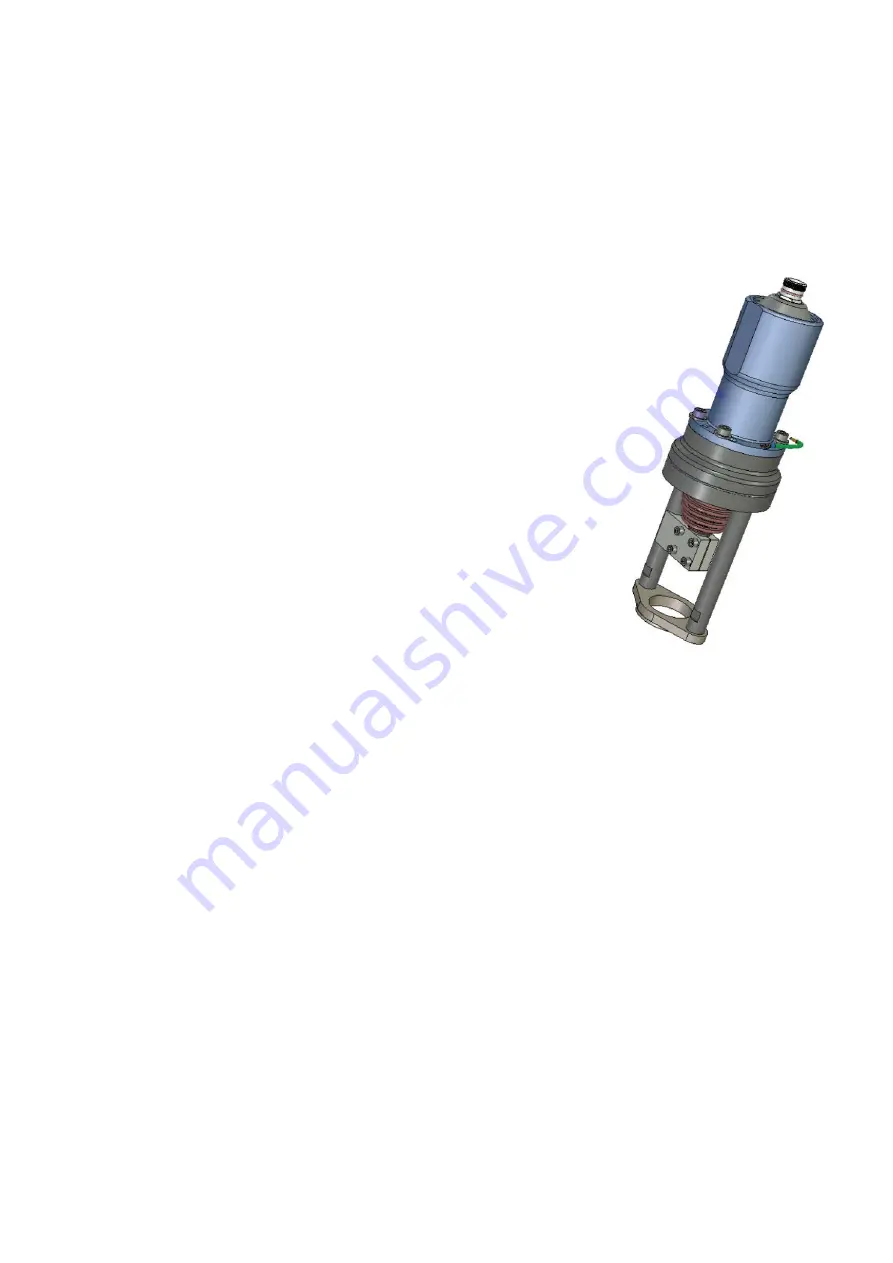
P30L1 consists of:
−
P30BU
−
30L1 Linear unit (max. 40 or 100 mm stroke, 10 mm screw pitch)
−
Linear adapter kit
1.
Turn the coupling gear by hand in 30L1 clockwise to its stop position.
2.
Fit the valve flange to the valve.
3.
Fit the bars to the 30L1. Then fit the unit to the valve flange.
4.
Put the valve spindle in maximum opened position.
5.
Turn the coupling gear counter clockwise until the ball screw end part hits the
end part of the valve spindle.
6.
Put the two spindle adapters in place and use the four clamp screws to secure
a good fit in the spindle thread and the ball screw thread and to one of the
bars. Adjust the clamp screw setting to get about 0,1 mm clearance to the bar.
7.
Check by rotating the gear coupling in the 30L1 that you get a smooth action
and that there is a small guiding clearance between the spindle adapter and the
rod along its stroke.
NB Check that the working range of the valve is within the working range of the 30L1 Linear module.
8.
Place the radial seal on the visible gear of P30BU.
9.
Attach P30BU to the 30L1 using the four M8x60 screws, washers and put Loctite 243 in the threads.
10.
The ground wire (green/yellow) which is fitted to the actuators flange should be connected to a suitable
ground point at the valve.
11.
All threads should be locked by using Loctite 243.
12.
Perform a Power Calibration (see section 6).
Summary of Contents for P220L
Page 1: ...User s guide installation and maintenance manual oden p30 Oden Control www odencontrol se ...
Page 21: ......
Page 22: ......
Page 23: ......
Page 24: ......


