


52
VT 4.0 OPERATING MANUAL
© 2002 Design, 2011
Doc. No. 12-5213-r02 (9/6/11)
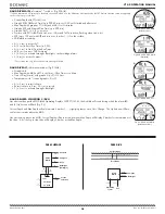
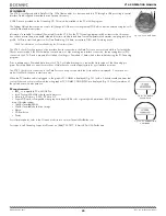
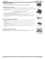
Battery Removal
• Remove the Retaining Bar located across the lower portion of the Battery (Fig. 135a).
• Remove the Cover O-ring. DO NOT use tools
• Using care not to damage the Battery Contacts (Fig. 135 b/c), slide the Battery up and out of the right side of the Battery
Compartment.
DO NOT allow a metal object to short circuit the top of the Battery which is positive (+) to the negative
( - ) contact of the Compartment.
Inspection
• Closely check all of the sealing surfaces for any signs of damage that might impair proper sealing.
• Inspect the Buttons, Lens, and Housing to ensure they are not cracked or damaged.
• Remove the Battery Cover O-ring and inspect it for any signs of deterioration or deformity. DO NOT use tools to remove the
O-ring.
• To ensure proper sealing, O-ring replacement is highly recommended each time the Battery is replaced.
• Closely examine the Battery Cover and Housing for any signs of damage that might prevent proper threading.
• Closely examine the inside of the Battery Compartment for any signs of corrosion indicating entrance of moisture into the
unit.
WARNING: If damage, moisture, or corrosion is found, return your unit to an Authorized Oceanic
Dealer, and DO NOT attempt to use it until it has received factory prescribed service.
VT 4.0 Battery Installation
• Slide a new 3 volt CR2450 Lithium Battery, negative (
-
) side down into the cavity of the battery compartment. Slide it in
from the right side and ensure that it slides under the contact clip on the left rim of the cavity.
• Orient the Retaining Bar across the lower portion of the Battery (Fig. 136a) and carefully push it down into position.
• Replace the Cover O-ring with a new one which must be a genuine Oceanic part that can be purchased from an Authorized
Oceanic Dealer.
Use of any other O-ring will void the warranty.
• Lightly lubricate the new Cover O-ring with silicone grease and place it on the inner rim of the Battery Cover (Fig. 137a),
and ensure that it is evenly seated.
• Slide the Cover Ring, top portion first (small opening), onto your thumb.
• Carefully place the Cover (with O-ring) into position on the rim of the Battery Compartment, then press it completely and
evenly down into place with your same thumb.
• Maintain the Cover securely in place and, using your other hand, slide the Cover Ring off your thumb and into position
around the Battery Compartment. The tabs on the Ring fit down into the slots located at the 2 and 9 o'clock positions.
• Using your fingers, turn the Ring counter clockwise 5 degrees until the tabs engage, then tighten it 5 more degrees by turning
it counter clockwise with the aide of a small blade screwdriver or spanner tool, pressing against the upper/left arm of the
Ring (Fig. 138).
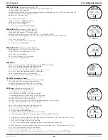
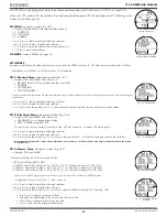
Testing
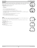
> Ensure that the LCD is clear and sharp in contrast. If any portions are missing or appear dim, or if a Low Battery condition is
indicated, return the VT 4.0 with Transmitter to an Authorized Oceanic Dealer for evaluation before use.
> During 24 hours after completion of a dive, the graphic DATA with selections SAVE ? and CLEAR ? will be displayed (Fig.
139) giving you the option to retain or delete settings and Ni-O2 calculations for repetitive dives.
• A (< 2 sec) to toggle between SAVE and CLEAR.
• S (< 2 sec) to save the selection.
> Graphics DATA SAVED (or CLEARED) with CAL COMPASS appear for 3 seconds (Fig. 140), then operation reverts to the
Compass CAL screen.
> Calibrate the Compass.
Refer to page 47.
> Verify all Set Points prior to diving.
• Pressurize the Regulator assembly (with Transmitter).
• Verify that the Link icon is displayed.
• Check the TMT Status screens.
Refer to page 14.
Fig. 135 - BATTERY
COMPARTMENT
a
c
b
Fig. 136 - VT 4.0 BATTERY
INSTALLED
a
Fig. 137 - COVER & RING
INSTALLATION
a
Fig. 138 - TIGHTENING
COVER RING
Fig. 139 - SELECT ITEM
Fig. 140 - DATA HAS BEEN
SAVED
Summary of Contents for VT 4.0
Page 4: ...4 VT 4 0 OPERATING MANUAL 2002 Design 2011 Doc No 12 5213 r02 9 6 11 FEATURES FUNCTIONS...
Page 10: ...10 VT 4 0 OPERATING MANUAL 2002 Design 2011 Doc No 12 5213 r02 9 6 11 NORM SURFACE MODES...
Page 19: ...19 VT 4 0 OPERATING MANUAL 2002 Design 2011 Doc No 12 5213 r02 9 6 11 DIVE MODE FEATURES...
Page 24: ...24 VT 4 0 OPERATING MANUAL 2002 Design 2011 Doc No 12 5213 r02 9 6 11 NORM DIVE MODES...
Page 31: ...31 VT 4 0 OPERATING MANUAL 2002 Design 2011 Doc No 12 5213 r02 9 6 11 GAS TMT SWITCHING...
Page 34: ...34 VT 4 0 OPERATING MANUAL 2002 Design 2011 Doc No 12 5213 r02 9 6 11 GAUG OP MODE...
Page 39: ...39 VT 4 0 OPERATING MANUAL 2002 Design 2011 Doc No 12 5213 r02 9 6 11 FREE DIVE OP MODE...
Page 44: ...44 VT 4 0 OPERATING MANUAL 2002 Design 2011 Doc No 12 5213 r02 9 6 11 COMPASS MODE...
Page 55: ...55 VT 4 0 OPERATING MANUAL 2002 Design 2011 Doc No 12 5213 r02 9 6 11 TECHNICAL DATA...


