


20
VT 4.0 OPERATING MANUAL
© 2002 Design, 2011
Doc. No. 12-5213-r02 (9/6/11)
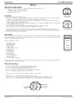
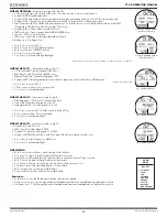
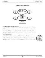
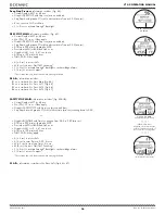
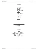
TRANSMITTER SIGNAL RECEPTION GUIDE
Best.
Reception.
Area
Poor
Reception.
Area
Poor
Reception.
Area
Poor
Reception.
Area
Poor
Reception.
Area
Poor
Reception.
Distance
(greater.than.4.feet/1.2.meters)
PROXIMITY OF THE TMTS (Transmitters) AND VT 4.0
The TMTs emit low frequency signals that radiate out in semicircular patterns parallel to the length dimension of the TMT. A coiled
antenna inside the VT 4.0 receives the signals when it is positioned within a zone parallel to or at a 45 degree angle to the TMT
as illustrated.
The VT 4.0 cannot effectively receive a signal when it is held out to the sides of the TMT or held at distances greater than 4 feet
(1.2 meters) in front of the TMT. Best reception is achieved when the VT 4.0 is within less than 4 feet (1.2 meter) of the TMT.
When installed into the high pressure ports of the Regulator First Stages, the TMTs must be positioned so that they face horizon-
tally outward from the Tank Valves.
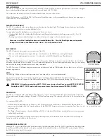
Link Interruption Underwater
During a dive, you may at times move the VT 4.0 out of the signal pattern of the TMT, resulting in a temporary loss of the Link
signal. The Link will be restored within 4 seconds after the VT 4.0 is moved back into its correct position.
An interruption may also occur while the VT 4.0 is within 3 feet (1 meter) of a running DPV, or shortly after a Strobe flashes. The
Link will be restored within 4 seconds after the VT 4.0 is moved out of that area.
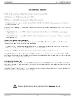
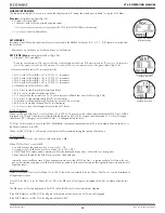
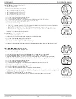
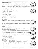
If the Link is not restored within 15 seconds, the Audible will sound, and the graphics LOST TMT, Pressure value, and Link icon
will flash (Fig. 37) until it is restored.
Fig. 37 - LOSS OF LINK
Summary of Contents for VT 4.0
Page 4: ...4 VT 4 0 OPERATING MANUAL 2002 Design 2011 Doc No 12 5213 r02 9 6 11 FEATURES FUNCTIONS...
Page 10: ...10 VT 4 0 OPERATING MANUAL 2002 Design 2011 Doc No 12 5213 r02 9 6 11 NORM SURFACE MODES...
Page 19: ...19 VT 4 0 OPERATING MANUAL 2002 Design 2011 Doc No 12 5213 r02 9 6 11 DIVE MODE FEATURES...
Page 24: ...24 VT 4 0 OPERATING MANUAL 2002 Design 2011 Doc No 12 5213 r02 9 6 11 NORM DIVE MODES...
Page 31: ...31 VT 4 0 OPERATING MANUAL 2002 Design 2011 Doc No 12 5213 r02 9 6 11 GAS TMT SWITCHING...
Page 34: ...34 VT 4 0 OPERATING MANUAL 2002 Design 2011 Doc No 12 5213 r02 9 6 11 GAUG OP MODE...
Page 39: ...39 VT 4 0 OPERATING MANUAL 2002 Design 2011 Doc No 12 5213 r02 9 6 11 FREE DIVE OP MODE...
Page 44: ...44 VT 4 0 OPERATING MANUAL 2002 Design 2011 Doc No 12 5213 r02 9 6 11 COMPASS MODE...
Page 55: ...55 VT 4 0 OPERATING MANUAL 2002 Design 2011 Doc No 12 5213 r02 9 6 11 TECHNICAL DATA...


