Ocean Technology Systems PowerCom 3000D User Manual Download Page 13

7

O

TS  PO
WER

CO

START-UP GUIDE 

Before diving, ensure the Lithium-Ion battery is fully charged.

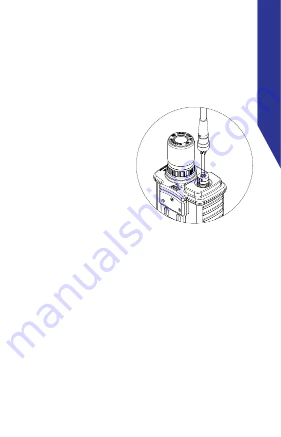
To charge the battery, remove the Earphone/Microphone (EM) cable by 

unscrewing the locking collar that retains the cable to the connector  in a 

counter-clockwise direction on the top of the housing. With the collar free, 

grip the connector and pull straight up WITHOUT twisting to disconnect the 

cable. Then, connect the battery charger to the corresponding connector on 

the PowerCom.

When connecting the Battery 

Charger Cable to the PowerCom 

unit, take caution when mating the 

connectors. Ensure the two larger 

guide pins are correctly aligned 

with the two larger sockets. Do 

not force the connectors to mate. 

Connection should be smooth 

when the pins are aligned with 

the sockets. Excessive force 

could result in connector failure or 

breakage.

When the Battery Charger is 

connected to the unit, the LED 

on the Battery Charger will turn GREEN then switch to RED if the battery 

requires a charge. If not, the LED will remain GREEN to indicate the battery 

is full. 

The LED on the Powercom unit is a single color LED.  When lit, it indicates 

the unit is charging or activated.  

Disconnect the Battery Charger from the unit and connect your EM Cable to 

the EM Assembly connector.

Your PowerCom is now ready for use.

The unit was designed to automatically turn on when it comes in contact 

with water. The two metal posts between the transducer and the connector 

on top of the unit are the water switch. To check or adjust your settings prior 

to dive, the unit can be turned on by placing a metallic object (like a small 

screwdriver) onto the two metal posts. Remove the metallic object after you 

have confirmed your settings. The unit will automatically shut off after 30-40 

seconds. Do not leave the metallic object on the unit as doing so will drain 

the battery.

Summary of Contents for PowerCom 3000D

Page 1: ...User Manual...

Page 2: ...e the suitability of the product for intended use and the user assumes all risk and liability whatsoever in connection therewith Neither Seller nor Manufacturer shall be liable either in tort or in co...

Page 3: ...the battery during use Care must be taken to ensure the battery is not damaged If the battery will not take a charge LED on the charger does not switch from Red to Green after about 2 hours discontinu...

Page 4: ...contact with another battery Do not use this battery for other application If the battery is completely drained charging will be necessary to maintain the health of the battery Do not leave a complete...

Page 5: ...t disassemble or reconstruct the battery Do not throw drop or cause impact to the battery Do not pierce a hole or puncture the battery with sharp objects Do not use any other batteries or cells in thi...

Page 6: ...v OTS POWERCOM...

Page 7: ...Channel 10 Volume 10 Squelch 10 Transmit 11 Scrambler 11 Battery Charging 12 Low Battery Indicator 12 Battery Disposal 12 Maintenance 12 PRE DIVE PROCEDURE FOR ESTABLISHING COMMUNICATIONS 12 POST DIVE...

Page 8: ...ure scrambler mode for more secure communications to our other wireless communication units We have also increased the modularity of the system that allows for ease of servicing options for cable leng...

Page 9: ...smitter VOX or manual activation Push To Talk PTT Transmitter Band PowerCom 3000 31 33 kHz 4 channel PowerCom 5000 25 33 kHz 8 channel Battery Type Rechargeable Lithium Ion Battery Housing Injection m...

Page 10: ...er O ring 283003 000 Earphone Microphone Connector Main Housing Belt Clip 137084 000 Housing O ring 283058 000 Rubber Armored Base O ring 283059 000 Microprocessor controlled Smart Battery 910505 000...

Page 11: ...lies MAIN HOUSING The main housing of the unit contains the electronics and battery compartment of the system The connectors to the Transducer and the Earphone Microphone cables are user replaceable T...

Page 12: ...umber Description 910496 000 OTS Guardian FFM Hot Mic Dual Earphone PTT Control HiUse 910379 000 OTS Guardian FFM Super Mic Dual Earphone PTT Control HiUse 910369 006 OTS Guardian FFM Hot Mic Dual Ear...

Page 13: ...e or breakage When the Battery Charger is connected to the unit the LED on the Battery Charger will turn GREEN then switch to RED if the battery requires a charge If not the LED will remain GREEN to i...

Page 14: ...ditional choices A table of the complete menu is provided Depress the PTT button again whenever you hear the option you want Once a change has been made the unit will repeat your choice then exit For...

Page 15: ...PowerCom 3000D 2 3 4 5 6 7 PowerCom 5000D 8 Volume Receive Low Medium High Extra High Side Low High Squelch On Low Med High Off Transmit VOX Low High Push To Talk Scrambler On Off Settings indicated...

Page 16: ...phone Assembly Side or Side Tone is how loud you hear yourself Side Tones is also useful for confirmation the transmitter is working If the unit has an issue where you are not transmitting you will no...

Page 17: ...sing this feature The system first has to detect that you have started speaking and will often clip your first word When you are finished speaking it takes a brief time to recognize that there is no m...

Page 18: ...Lithium Ion battery and the Battery Charger in accordance with the local state and federal electronic waste recycling regulations Do not discard them in the trash MAINTENANCE Routine maintenance of t...

Page 19: ...he unit in freshwater for several mintues or until the unit is clean A mild soap solution may be used to remove contaminants and after cleansing rinse with freshwater 2 Dry the transceiver with a clea...

Page 20: ...Contact OTS Transmission setting stuck on PTT Contact OTS No Side Volume Contact OTS Charger LED illuminates green but the unit LED does not activate Contact OTS Charger LED illuminates green unit LED...

Page 21: ...ling Screw O rings 2 years Battery Base and Housing O rings 2 years Cable As Required Transducer As Required Note If the unit is opened for any reason be sure to inspect the O rings for any damage or...

Page 22: ...ants Use of silicone based lubricants will void any warranties If you need spare parts contact us at SALES OTSCOMM COM or 714 754 7848 BATTERY REPLACEMENT 1 Using a large flat head screw driver loosen...

Page 23: ...he rubber of the O Ring Ensure the O ring rests compeletly inside the groove 4 To replace the Sealing Screw O rings there is a second set of threads in the Rubber Armored Base continue to unscrew by p...

Page 24: ...ghten the screws Do not over torque the screws SPARE PART ORDERING INSTRUCTIONS Spare parts are available to purchase from OTS To Purchase contact OTS at SALES OTSCOMM COM Name Part Number Main Housin...

Page 25: ...h the distance from the source As the sound passes through the water some of the energy is converted to heat and some energy is scattered by fish pilings seaweed bubbles etc In addition both the surfa...

Page 26: ...positioned l 000 yards from the source but may reach a deeper detector position further from the source Greater temperature variations can cause these paths to bend more sharply The best method to de...

Page 27: ...he backside of the blocking object a zone of silence is formed in which reception of the transmitted signal is not possible Divers can reduce zones of silence by moving away from around or above the b...

Page 28: ...factory trained center or properly trained personnel In no event shall OTS be liable for consequential damages related to our product s Warranty registration is required Any parts requiring replaceme...

Reviews: