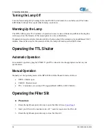
background image


2: HPX-2000 Specifications 

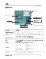
Rear Panel 


Component Description 

Voltage Selector Switch 

Select regional voltage setting for lamp (AC 230-240V, 50/60Hz or AC 110-115V, 
50/60Hz). 

Main Power Switch 

Turn on to supply power to the HPX-2000. The Power LED lights when this switch 
is in the On position. 

Fuse Compartment 

Contains the fuse to protect the unit against overload: 

Fuse Type: Miniature fuse 5 x 20 mm, 1 Amp slow blow 

Input Terminal for Power 
Cord 

Plug power cord into this terminal. 

Note:

 Only connect the power cable to the lamp when the Main Power Switch is in 

the OFF position. 

TTL Input 

SUB-D 15-pin connector for automatic shutter control. 

Type Sign 

Label providing lamp information:  
- Type   


High Power Xenon Lightsource 

- Version 


Europe / USA 

Order-No. 

  HPX-2000 

Serial-No. 

  Xxxxxx 

- Mains connection 


115 / 230V 47-63Hz 

- Power consumption 


50 Watt 

- Max. Ambient Temperature 

35°C 

Cooling Fan 

Cools the interior of the HPX-2000. Do not obstruct. 

TTL Input 

Type Sign 

Fuse Compartment 

Main Power Switch 

Input Terminal for 
Power Cord 

Voltage Selector Switch

Cooling Fan 

000-10000-080-02-0505 

5


Summary of Contents for HPX-2000

Page 1: ...Fri EST Ocean Optics B V Europe Geograaf 24 6921 EW DUIVEN The Netherlands Phone 31 0 26 3190500 Fax 31 0 26 3190505 E mail Info OceanOptics com General sales inquiries Info OceanOpticsBV com European...

Page 2: ...2005 Ocean Optics Inc All rights reserved No part of this publication may be reproduced stored in a retrieval system or transmitted by any means electronic mechanical photocopying recording or otherwi...

Page 3: ...pment There are no warranties for the Xenon Bulb HPX 2000 B and the Xenon Bulb Module HPX 2000 BM This instrument should not be used for any Clinical or Diagnostic purposes Data generated in these are...

Page 4: ...Important Safety Notices B 000 10000 080 02 0505...

Page 5: ...ct Related Documentation iii Upgrades iv Chapter 1 Setup 1 Overview 1 Unpacking the HPX 2000 2 Contents 2 Connecting the Fiber Optic Cable 2 Chapter 2 HPX 2000 Specifications 3 Operating Environment 3...

Page 6: ...Power 9 Starting the Lamp 9 Turning the Lamp Off 10 Warming Up the Lamp 10 Operating the TTL Shutter 10 Automatic Operation 10 Manual Operation 10 Operating the Filter Slit 10 Chapter 4 Troubleshooti...

Page 7: ...he15 DB 15 connector Chapter 3 Operating Instructions Provides instructions for operating the Xenon lamp and the TTL shutter Chapter 4 Troubleshooting Contains a table of troubleshooting information A...

Page 8: ...cs to make a change or an upgrade to your system To facilitate these changes you must first contact Customer Support and obtain a Return Merchandise Authorization RMA number Please contact Ocean Optic...

Page 9: ...n unpacking and setting up your HPX 2000 High power Xenon Light Source Before using the HPX 2000 for the first time check for transport damage Be sure to adhere to all warnings on the unit and in this...

Page 10: ...cessary 3 Use this instrument in a clean laboratory environment see Operating Environment Contents Your HPX 2000 package should contain the following HPX 2000 High power Xenon Light Source Power cord...

Page 11: ...Unit Moisture Is designed for operation in dry rooms only Ventilation Should be situated so that its location or position does not interfere with proper ventilation Heat Should be situated away from...

Page 12: ...hutter closed TTL operation by external TTL signal HIGH OPEN LOW CLOSE Mechanical Protection SMA Connector Covered to protect users from unintentionally looking directly at the beam of light Used for...

Page 13: ...er Cord Plug power cord into this terminal Note Only connect the power cable to the lamp when the Main Power Switch is in the OFF position TTL Input SUB D 15 pin connector for automatic shutter contro...

Page 14: ...Shutter PIN 13 TTL PIN 10 Ground Filter Dimensions possible Up to diameter or square 25mm x 4mm or 20 x 6 mm Input Line 115 230VAC switchable Markings Directives CE VDI VDE 0160 EN 61010 Input Current...

Page 15: ...lowing table contains pinout information for the HPX 2000 Light Source Pin Description 1 na 2 na 3 na 4 na 5 na 6 na 7 na 8 na 9 na 10 Ground 11 na 12 na 13 TTL Signal Shutter control 14 na 15 na na n...

Page 16: ...2 HPX 2000 Specifications 8 000 10000 080 02 0505...

Page 17: ...onnect the power cord to the Terminal Input on the rear panel of the unit 3 Turn the Main Power Switch ON The Power LED lights indicating that the unit is receiving power Starting the Lamp Hold the Xe...

Page 18: ...ed up for this amount of time the lamp will reach specified drift values Operating the TTL Shutter Automatic Operation For automatic operation plug the SUB D 15 pin TTL connector into the appropriate...

Page 19: ...esolution Line power not present Check line voltage Power switches on but no LEDs light Fuse defective Check fuse Lifetime of the lamp is exhausted Replace the lamp module Xenon lamp does not start La...

Page 20: ...4 Troubleshooting 12 000 10000 080 02 0505...

Page 21: ...er Switch OFF Caution Connection disconnection of the power cord from the Xenon lamp MUST only be done when the Main Power Switch is turned OFF Because the output of the power supply is not galvanical...

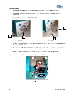
Page 22: ...PX 2000 Figure 1 Figure 1 Figure 2 2 4 1 3 8 Loosen the screws Figure 3 5 by hand disconnect the plug Figure 3 6 and remove the old bulb from the HPX 2000 9 Place the new HPX 2000 BM bulb inside the h...

Page 23: ...cable connecting 2 filter slit 10 O operating environment 3 P package contents 2 parts list 6 pinouts 7 product related documentation iii S setup 1 specifications 3 6 T troubleshooting table 11 TTL s...

Page 24: ...Index 16 000 10000 080 02 0505...

Reviews: