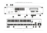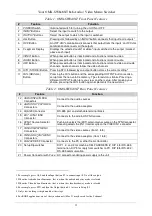
Your OMX-SW8x8NT 8x8 Audio / Video Matrix Switcher
4
Table 1: OMX-SW8x8NT Front Panel Features
#
Feature
Function
1
POWER
Switch
Illuminated switch for turning the unit ON or OFF
2
INPUT
Buttons
Select the input to switch to the output
3
OUTPUT
Buttons
Select the output to which the input is switched
4
ALL
Button
Pressing
ALL
followed by an
INPUT
button, connects that input to all outputs
1
5
OFF
Button
An
OFF
-
OUT
combination disconnects that output from the inputs; an
OFF
-
ALL
combination disconnects all the outputs
6 7-segment
Display
Displays the selected audio
2
or video
3
input switched to the output (marked
above each input)
7
VIDEO
Button
When pressed button is illuminated and all actions relate to video
8
AUDIO
Button
When pressed button is illuminated and all actions relate to audio
9
AFV
Button
When pressed button is illuminated and all actions relate to video and audio
channels. Audio channels follow the video channels
10
STO
(STORE) Button Pressing STO followed by an output button stores the current setting
4
11
RCL
(
RECALL
)
Button
Pressing the
RCL
button and the corresponding OUTPUT button recalls a
setup from the non-volatile memory. The stored status blinks. Pressing a
different OUTPUT button lets you view
5
another setup. After making your
choice, pressing the
RCL
button again implements the new status
Table 2: OMX-SW8x8NT Rear Panel Features
#
Feature
Function
12
AUDIO INPUTS
RCA
Connectors
Connect to the audio sources
13
AUDIO OUTPUTS
RCA
Connectors
Connect to the audio acceptors
14
RS-485
Connector
RS-485 port on detachable terminal block
15
EXT. SYNC
BNC
Connector
Connects to the external SYNC source
16
SYNC
Source
Selector
Button
Pushing in selects the (EXT) external sync source on the SYNC connector;
releasing selects the (IN 1) internal sync on the VIDEO IN 1 connector
17
VIDEO INPUTS
BNC
Connectors
Connect to the video sources (from 1 to 8)
18
VIDEO OUTPUTS
BNC
Connectors
6
Connect to the video acceptors (from 1 to 8)
19
RS-232
DB 9F Connector
Connects to the PC or other Serial Controller
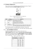
20 Setup Dipswitches
DIP 1, 2, and 3 for machine SELF ADDRESS #; DIP 4 for RS-485
termination, DIP 5 for reply from switcher to PC, DIP 8 for RS-232 /
RS-485 communication
21 Power Connector with
Fuse
AC connector enabling power supply to the unit
1 For example, press ALL and then Input button # 2 to connect input # 2 to all the outputs
2 When the Audio button illuminates, that is, when the audio breakaway mode is selected
3 When the Video button illuminates, that is, when the video breakaway mode is selected
4 For example, press STO and then the Output button # 3 to store in Setup # 3
5 Only view, nothing is implemented at this stage
6 For RGBS applications, one of the sync channels (H or V) may be used for the S channel
Summary of Contents for OMX-SW8X8NT
Page 1: ...OMX SW8x8NT ...


