background image

2

©2021 OBSIDIAN CONTROL SYSTEMS  all  rights  reserved.  Information,  specifications,  diagrams, 

images, and instructions herein are subject to change without notice. Obsidian Control Systems logo 

and identifying product names and numbers herein are trademarks of ADJ PRODUCTS LLC. Copyright 

protection claimed includes all forms and matters of copyrightable materials and information now allowed 

by statutory or judicial law or hereinafter granted. Product names used in this document may be trademarks 

or registered trademarks of their respective companies and are hereby acknowledged. All non-ADJ brands 

and product names are trademarks or registered trademarks of their respective companies.
OBSIDIAN CONTROL SYSTEMS and all affiliated companies hereby disclaim all liabilities for property, 

equipment, building, and electrical damages, injuries to any persons, and direct or indirect economic loss 

associated with the use or reliance of any information contained within this document, and/or as a result 

of the improper, unsafe, insufficient and negligent assembly, installation, rigging, and operation of this 

product.
ELATION PROFESSIONAL B.V.

Junostraat 2 | 6468 EW Kerkrade, The Netherlands

+31 45 546 85 66
FCC STATEMENT

This device complies with Part 15 of the FCC Rules. Operation is subject to the following two conditions: (1) 

this device may not cause harmful interference, and (2) this device must accept any interference received, 

including interference that may cause undesired operation.
FCC RADIO FREQUENCY INTERFERENCE WARNINGS & INSTRUCTIONS

This product has been tested and found to comply with the limits as per Part 15 of the FCC Rules. These 

limits are designed to provide reasonable protection against harmful interference in a residential installation. 

This device uses and can radiate radio frequency energy and, if not installed and used in accordance with 

the included instructions, may cause harmful interference to radio communications. However, there is 

no guarantee that interference will not occur in a particular installation. If this device does cause harmful 

interference to radio or television reception, which can be deter- mined by turning the device off and on, 

the user is encouraged to try to correct the interference by one or more of the following methods:

•  Reorient or relocate the device.

•  Increase the separation between the device and the receiver.

•  Connect the device to an electrical outlet on a circuit different from which the radio receiver is connected.

•  Consult the dealer or an experienced radio/TV technician for help.
Energy Saving Matters (EuP 2009/125/EC)

Saving electric energy is a key to help protecting the environment. Please turn off all electrical products 

when they are not in use. To avoid power consumption in idle mode, disconnect all electrical equipment 

from power when not in use. Thank you!

Document Version: An updated version of this document may be available online.

Please check 

www.obsidiancontrol.com

 for the latest revision/update of this document before beginning 

installation and use.

Date

Document Version

Note

27/12/2021

1

Initial Release

Summary of Contents for NETRON EP2

Page 1: ...1...

Page 2: ...ce that may cause undesired operation FCC RADIO FREQUENCY INTERFERENCE WARNINGS INSTRUCTIONS This product has been tested and found to comply with the limits as per Part 15 of the FCC Rules These limi...

Page 3: ...IEW 5 CONNECTIONS 6 MENU 8 NAVIGATION 8 HOME SCREEN 8 PRESETS 9 NETRON PRESETS 10 DMX PORTS 11 VIEW AND TEST 12 IP ADDRESS 13 SYSTEM 14 INFORMATION 15 WEB REMOTE CONFIGURATION 16 WEB REMOTE MENU 17 FI...

Page 4: ...n CUSTOMER SUPPORT Contact your local Obsidian Controls Systems dealer or distributor for any product related service and support needs Also visit forum obsidiancontrol com with questions comments or...

Page 5: ...Display with rotary knob Remote configuration via internal webpage Powder coated compact aluminum housing Connect to ONYX PC for a full four Universe Solution In wall On Wall Truss and Standalone mou...

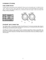
Page 6: ...cted 5 Not connected ETHERNET DATA CONNECTION The Ethernet cable is connected on the side of the EP2 device This device cannot be daisy chained Although this is an Locking RJ45 Ethernet connector and...

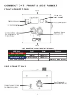
Page 7: ...ash on RDM packets DMX PORTS STATUS INDICATOR LEDs CONNEC T IO N S FRONT SIDE PANEL S FRON T C O NNECTIONS 2 5Pin DMX ports are bidirectional for In and Output DMX Port Status Indicator LED RJ45 Netwo...

Page 8: ...arrow Wheel Right Scroll down in menu list increase values Wheel Left Scroll up in menu list decrease values Wheel Push Enter Menu Select menu item go down one level in menu confirm values Back Arrow...

Page 9: ...ets 2 ArtNet 10 x Universe 1 32767 3 ArtNet 192 x Universe 1 32767 4 ArtNet 172 x Universe 1 32767 5 ArtNet DHCP Universe 1 32767 6 ArtNet In Universe 1 32767 7 ArtNet In Thru Universe 1 32767 8 sACN...

Page 10: ...es Artnet 172 x Automatic 172 x 255 0 0 0 Artnet Universe Output Output X X X 1 RDM Yes Artnet DHCP DHCP DHCP Artnet Universe Output Output X X X 1 RDM Yes Artnet In Automatic 2 x 255 0 0 0 Artnet Uni...

Page 11: ...ce SUB MENU OPTION VALUES DESCRIPTION Mode Disable The port is disabled Input The port receives DMX values and assigns them to the selected Universe Output The port sends out DMX Values on the selecte...

Page 12: ...e Encoder to dial to the desired DMX address Push Encoder to change display readout style Grid List Address sACN View Universe 1 32767 View a specific sACN Universe Start Monitor Start Monitoring Valu...

Page 13: ...ce waits for a DHCP server address After30sitassignsitselfaunique169 254 x x address but continues to monitor DHCP server requests Automatic 2 x The device is set to a unique 2 x x x Address Subnet 25...

Page 14: ...No DMX is sent until valid data is received for the ports The last incoming values continue to be sent on the ports until the time is expired Once timeout has completed the device will perform one of...

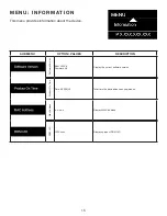
Page 15: ...e SUB MENU OPTION VALUES DESCRIPTION Software Version Boot SW V Firmware V Display the current software version Product On Time Time XXXXX H Total time the device has been powered on Mac Address x x x...

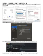
Page 16: ...are in the same IP address range and are connected Browser Sample Enter the device IP address into a web browser to access the device page PC Configuration Sample Please note your PC configuration res...

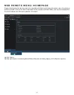
Page 17: ...oft Internet Explorer Also the antivirus software AVAST is known to block important communication with NETRON and must be disabled for the web interface and firmware updates to function Identify Butto...

Page 18: ...18 WEB REMOTE MENU PRESETS NETRON PRESETS WEB REM O T E M E N U PR ESETS USER PR ESETS...

Page 19: ...19 WEB REM O T E M E N U DMX PORTS OUTP UT...

Page 20: ...20 WEB REM O T E M E N U DMX PORTS DISABLE WEB REM O T E M EN U DMX P ORTS INP UT...

Page 21: ...21 WEB REM O T E M E N U DMX PORTS SEND VALUE...

Page 22: ...22 WEB REM O T E M E N U DMX PORTS SEND VALUE...

Page 23: ...23 WEB REMOTE MENU DMX PORTS DEVICE SETTINGS...

Page 24: ...24 WEB REMOTE MENU DMX PORTS MAINTENANCE...

Page 25: ...update process The update is provided in two files Display NFW and Web IMG Both need to be installed for a full upgrade Reset to factory defaults Reload the configuration file from the web interface...

Page 26: ...26...

Reviews: