Oberheim MC 3000 Operating Manual Download Page 41

MC 3000

Operating Manual

111

Bear in mind that the MIDI FILTER settings affect the data processed by the instrument
(control channel and IN/OUT redirection of the patch-bay) while they have no effect on
the MIDI THRU ports.

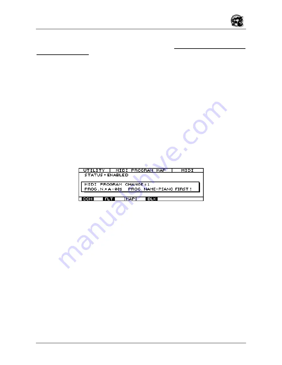
6.2.4  MIDI PROGRAM MAP (MAP)

The MIDI PROGRAM MAP is accessed from the previous page or from any other page of
the COMMON section by pressing F3, in line with the icon rectangle marked MAP.  As in
all the other pages, the top of the page displays the operating mode, the page and the
current section, while the bottom carries the icons associated to the various pages of the
section, with the icon of the current page highlighted by reverse lighting.

This page enables the user to create a personalized map where he can set the order of
the patches which can be recalled by a remote unit with consecutive program change
numbers.  In other words, the user can make settings which mean that program change n.
1 does not necessarily correspond to patch n. 1 of selected bank, program change n. 2
does not correspond to patch n. 2, and so on.  For example, the user may have program
change n.1 correspond to patch 13 of bank D and n. 2 correspond to patch 3 of bank H,
and so on.  This function is useful when the remote unit is unable to send the bank
change message, and so using only program changes from 0 to 127, the user is forced to
use only the first 128 patches (0-127), of bank selected only.

Moving the cursor keys to the STATUS field in the top right-hand corner of the display, the
user can use the encoder or the INC and DEC keys to set the DISABLED status which
disables the personalized map of the program changes, or the MIDI PROGRAM MAP. In
this case, the program changes are received in the normal way and if the remote unit is
not capable of sending the bank change messages, the user will only be able to change
the patches of bank selected. If the user sets ENABLED in the STATUS field using the
INC and DEC keys or the encoder, the MIDI PROGRAM MAP will be enabled and each
program change number sent by the remote unit will correspond to a specific patch set
personally by the user and belonging to any bank he requires.

To set the map, use the cursor keys to move down into the central window of the display
and locate in the MIDI PROGRAM CHANGE.  Then use the encoder or INC and DEC to
set the number of the program change sent by the remote unit by the MC 3000.  After this,
use the cursor keys to move to the PROG. N. field in the left-hand corner of the central
window, and use the encoder or the numeric pad  to set the patch which will appear when
the remote unit sends that specific program change.  While this is done, the name of the
selected patch will also automatically appear in the right-hand side of the central window.

Repeat the entire procedure for all the associations you wish. All the modification will be
stored in memory automatically.

Summary of Contents for MC 3000

Page 1: ...MC 3000 Midi Master controller MANUALE OPERATIVO OPERATING MANUAL I GB Ver AA4...

Page 2: ...batnub washbowl kitchen sink in a wet basement or near a swimming pool or the like 4 This product either alone or in combination with an amplifier and headphones or speakers may be capable of produci...

Page 3: ...e mode keys 1 3 6 Using the mouse and its characteristics 1 3 7 The MC3000 MIDI ports and MIDI potential 1 3 8 The other items on the rear panel 2 Let s switch on the MC 3000 2 1 What the instrument d...

Page 4: ...4 6 Controllers CTL 4 6 1 Introduction 4 6 2 Sliders 4 6 3 Pedals 4 7 PATCH BAY 5 The CHAIN operating mode 5 1 Introduction 5 2 Play Chain 5 3 Edit Chain 6 The UTILITY operating mode 6 1 Introduction...

Page 5: ...it curves 6 6 1 Introduction 6 6 2 Dynamic curves 6 6 3 Aftertouch Curves 6 7 Tools 6 7 1 Introduction 6 7 2 Mouse Set up 6 7 3 Battery Status 6 7 4 Memory Status 6 7 5 Power on procedures 7 Additiona...

Page 6: ...the user to draw on a large quantity of data without having to wait for them to be loaded from a sequencer or a computer 1 3 LET S TAKE A LOOK AT THE INSTRUMENT and discover some if its features 1 3...

Page 7: ...pressed to return to the previous video page or the instrument s main menu page 1 3 4 The dynamic encoder the INC and DEC keys and the cursor keys Further to the right on the front panel we find a wh...

Page 8: ...hich the patch to be recalled is located This selection does not always start from bank A but starts from the bank current when the operation is carried out Finally we come to the ENTER key used to co...

Page 9: ...provided in the rear panel the mobile pointer used to select the various fields or icons on the screen appears on the display When using the mouse bear in mind that the left hand key selects the cent...

Page 10: ...monitor the entire flow of data in both DEC and HEX formats on the various ports The instrument offers the user 48 SYS EX tables with auto acquisition function it will therefore be possible to acquire...

Page 11: ...There may be 3 types of message the batteries are charged they are almost flat so the data stored inside the instrument should be saved the batteries are flat all user data can be lost Immediately aft...

Page 12: ...right of the front panel MODE section At this point the display will show the 6 sections of the UTILITY operating mode Select the number 6 TOOLS in the bottom right hand corner of your display using t...

Page 13: ...he POWER ON PROCEDURES page just described in the TOOLS section 6 of the UTILITY operating mode Now select the third line where the words PATCH POWER ON appear using the cursor keys to move around the...

Page 14: ...mode while the box in the top right hand corner indicates the activation status of the 8 zones in that patch the solid circles indicate the active zones which are being played while the empty ones sho...

Page 15: ...goes from patch n 00 to n 09 of the respective bank A At this point if we wish to display the groups which follow we simply press F6 located in line with the rectangle marked 10 in the bottom right ha...

Page 16: ...pear in the top of the display This page shows the setup of the splits and layers relating to the current patch Each letter which appears on the right and left of the display under the image of the ke...

Page 17: ...e Selection of zone D and detailed information about its key range Press F1 or ESC to leave this function and go to the TOP PAGE The function key F6 switches directly to the EDIT environment of the ZO...

Page 18: ...nder the word PAGE can be pressed to scroll through the successive subpages in increasing order up to 5 after which when F5 is pressed again the system returns to INFO 1 The name of the page INFO and...

Page 19: ...enever the MC 3000 is switched off On the other hand the volumes you assign to the zones in the EDIT environment can be saved and recognized as base volumes so whenever you switch on the instrument an...

Page 20: ...e directly to the Program Mode functions analyzed previously 3 6 PRG send program change FUNCTION The PRG send Program Change function which is the exclusive property of the TOP PAGE allows the user t...

Page 21: ...ng function key F6 SOLO icon This function keeps only the zone selected by the user active switching all the other zones currently active to Stand by status When the function key is pressed the follow...

Page 22: ...de the display will switch to the respective video pages structured as shown below A dash blinking under the first character of the name indicates that this character is selected and can be modified u...

Page 23: ...selected with the encoder or the cursor keys and confirming using ENTER Each section may consist of one or two pages To facilitate the edit procedures the MC 3000 allows the user to move around the 5...

Page 24: ...ANNEL specifies the MIDI channel on which the selected zone transmits its messages This may be modified using the same procedure the user locates the cursors in the TX CHANNEL field and modifies the M...

Page 25: ...mode message is a strictly MIDI datum and thus a transmission parameter so the keyboard is always polyphonic However for mono transmission the receiver unit must be capable of receiving in this mode...

Page 26: ...le when it was constructed Underneath the TABLE field is the PRG field with the PRG NAME field beside it PRG stands for program change and here the user can set the number of the program change assign...

Page 27: ...play indicates that the window is dedicated to setting of the auxiliary messages These messages do not form part of the current zone but may be sent together with it in order to control devices which...

Page 28: ...save these modifications press the WRITE key and follow the procedure described in point 3 8 4 5 CURVES CRV 4 5 1 Introduction The user may press F4 below the CVR icon from the previous page or any o...

Page 29: ...hown in reverse The last rectangle contains the word MORE F6 can be pressed for access to the second page of the section dedicated to the Aftertouch curves which can be assigned to the single zones 4...

Page 30: ...cted is dedicated to the sliders and is thus called SLIDERS Here again the top of the display contains the name of the current page the name of the current patch and the lights indicating the activati...

Page 31: ...following types of pedals Switch Pedals Pedals with a NORMALLY CLOSED contact Expression Pedals Pedals equipped with a stereo jack connector The input impedence must be included from 10 to 22 Kohm N B...

Page 32: ...the edit mode Follow the instructions given in point 3 8 to save the settings made 4 7 PATCH BAY This section can only be accessed from the EDIT mode menu page by pressing the function key F6 or locat...

Page 33: ...The user can now move on with the cursor keys to the second window on the column or logic line just connected to the input port where the connections between this MIDI IN and one or more OUT outputs...

Page 34: ...l window showing the 8 MIDI OUTs on logical line 1 Follow the procedures previously described to enable outputs 7 and 8 the first output is already selected by default Note that If the MIDI IN ports a...

Page 35: ...g the way in which the system is moved on to the next step this may be set by means of a pedal a number key a key note key etc The central window contains the information about the current step while...

Page 36: ...nwards one place down The function keys F5 and F6 are used to move forward or back one step respectively Whenever you move one step forward or back the central window will show you the number and name...

Page 37: ...ame procedure thus making up the new patch name All the function keys are enabled here F1 selects the INSERT writing mode where each character selected using the number pad is inserted if this mode is...

Page 38: ...function keys F5 and F6 5 If you wish to make corrections to any step position on the step F5 and F6 keys and delete the current step DEL or insert a new one INS 6 When last step is reached select the...

Page 39: ...ted using the relative key in the group of MODE keys on the right of the front panel is as shown below This video page shows all the sections of the UTILITY mode each of which can be accessed by selec...

Page 40: ...the MC 3000 does not have an internal sound generation system the messages it interprets are limited to Program Change Bank select patch selection and Exclusive bulk dump systems If any control change...

Page 41: ...ced to use only the first 128 patches 0 127 of bank selected only Moving the cursor keys to the STATUS field in the top right hand corner of the display the user can use the encoder or the INC and DEC...

Page 42: ...e form of exclusive codes The options available to the user are ALL The instrument s entire internal memory undergoes a Bulk Dump PROGRAMS Bulk Dump of the Programs CHAIN Bulk Dump of the data relatin...

Page 43: ...an be accessed by locating on the MIDI MONITOR field with the encoder or using the cursor keys and confirming with ENTER This is the only page in the section and thus also the only one automatically d...

Page 44: ...The MIDI channel of the message monitored appears in the first column on the right The type of event displayed is described in the second column The data relating to the type of event are shown in th...

Page 45: ...the physical behaviour of the 3 wheels the 8 pedals and the 8 sliders 6 4 2 WHEELS SET UP WHL The first page which appears when the SYSTEM CONTROL section is selected is called WHEELS SET UP The curso...

Page 46: ...m pedals as well as the OFF condition which disables the pedal These 14 controls have been chosen because they are generally used in a large number of patches They are 1 GENERAL SUSTAIN 2 GENERAL VOLU...

Page 47: ...s the cursor keys to locate on the value relating to the range of a pedal it will be highlighted and it can then be modified using the encoder the INC and DEC keys or the numeric pad If the value repr...

Page 48: ...sponding function key F6 Press ESC to exit from the range page and return to the UTILITY MASTER page 6 5 EDIT TABLES 6 5 1 Introduction The EDIT TABLES section is accessed from the UTILITY MASTER vide...

Page 49: ...the name move onto them using the cursor keys The bottom of the display contains icons associated to the function keys which are 1 INS which stands for insert meaning that the relative function key F1...

Page 50: ...le Therefore users who have a sound module are able to build up a specific table for that module The top field TABLES N P1 GENERAL MIDI represents the number and name of the selected Table The user ca...

Page 51: ...g to gradually rising tens 30 39 40 49 50 59 etc will appear Similarly to display the previous groups press F5 close to the rectangle marked 10 and whenever the key is pressed the groups of lower tens...

Page 52: ...ITE and the following video page will appear Here the display shows as display only the current location of the table which has been modified and allows the user to select its destination location 8 U...

Page 53: ...or the INC and DEC keys to select the output port through which the exclusive code messages can be sent by pressing ENTER The contents of the exclusive code to be sent appear in the bottom of the cen...

Page 54: ...the display informs us that when ENTER is pressed the MC 3000 presets to receive the exclusive message from the remote unit Once ENTER has been pressed the message WAITING FOR DATA appears on the dis...

Page 55: ...At this point the WRITE SYS EX subpage will return to the display and the user can decide whether to abort the procedure or save all the modifications by pressing ESC or WRITE respectively 6 6 EDIT C...

Page 56: ...ion channel are set After using the cursor keys to locate in the OUT or CH fields the user can use the encoder or INC and DEC to select the MIDI port and the MIDI channel to be used for transmission o...

Page 57: ...ient to be attributed to the section of curve set on the X axis pressure on the key by the START and END values while the Q field sets the shift of the same section of curve in relation to the x axis...

Page 58: ...tal mirror function is used to obtain a horizontal reflection of the curve in which the X values are reversed compared to the previous situation Original curve After HMIR function The VMIR vertical mi...

Page 59: ...name with a flashing cursor dash under its first letter appears in the centre of this screen The flashing cursor dash indicates that the letter can be modified with the encoder or the INC and DEC key...

Page 60: ...the video page otherwise CAPS OFF will appear The DONE icon associated to key F6 returns to the WRITE Dynamic video page where the user can save everything by pressing the WRITE key or abort the modif...

Page 61: ...only difference is in the axes which in this case represent the physical pressure applied to the key x axis and the respective MIDI Aftertouch value y axis To modify the values between the START and E...

Page 62: ...to obtain a horizontal reflection of the curve in which the X values are reversed compared to the previous situation Original curve After HMIR Function The VMIR vertical mirror function is used to ob...

Page 63: ...ch works exactly as described for saving dynamic curves in point 6 6 2 of this section N B In order to keep MIDI communications streamlined when a dynamic curve is created parallel to the X axis the s...

Page 64: ...he number associated to it with the encoder or the INC and DEC keys Moving one step lower using the down arrow cursor hey the user can use the INC and DEC keys or the encoder to set the MOUSE AUTOREPE...

Page 65: ...strument A graphic symbol of a micro chip appears on the right of the central window 6 7 5 POWER ON PROCEDURES The POWER ON PROCEDURES page can be accessed from the previous page or any page of the TO...

Page 66: ...r the INC and DEC keys or the alphanumeric keypad in which case the operation must be confirmed with ENTER The final rectangle in the bottom right hand corner marked LAST represents not a page but a s...

Page 67: ...LED During the self testing procedure which takes place whenever the instrument is switched on the keyboard does not respond to the control messages Contact an authorized service centre for a solution...

Page 68: ...TED The MC 3000 has noted ejection of the jack from the pedal connectors CTRL Control Change name A warning that a control change has been received on the MC 3000 control channel This control will be...

Page 69: ...rings relating to the MIDI OUT port DUMP OUT COMPLETED The Bulk Dump procedure has been terminated correctly DUMP OUT ABORTED The Bulk Dump procedure has been interrupted by the user and so the saving...

Page 70: ...reezing of the contents of the display without the presence of any data for monitoring or after the CLEAR key has been pressed the operations must be repeated HOLD ON NO CHANGE In the MINI MONITOR sec...

Page 71: ...the SECTION field indicates the MC 3000 allows the user to perform a SELECTIVE RESET meaning that the section and memory location to be initialized can be decided The options available to the user in...

Page 72: ...a series of messages which restore correct operation of the peripherals connected if specific stall conditions occur in the MIDI communications e g notes which sound indefinitely permanent Pitch Bende...

Page 73: ...re assignable to sliders and or pedals PROGRAM CHANGE True 0 127 0 127 0 127 1 2 SYSTEM EXCLUSIVE O O 1 3 SYSTEM Song Pos COMMON Song Sel Tune X X X X X X SYSTEM Clock REAL TIME Commands X X X X AUX L...

Page 74: ......

Page 75: ...since this version of the manual was completed The information contained in this version of the owner s manual supercedes all previous version NOTE This equipment has been tested and found to comply...

Page 76: ...869605 e mail viscount omniway sm Internet www viscount organs com www viscount it Distribution for Italy TITAN MUSIC S A Strada Genghe di Atto 80 47031 Acquaviva Repubblica di San Marino tel 0549 99...

Reviews: