background image

13

[330]

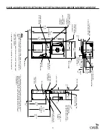
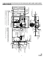
APPROX. WATER

SUPPLY LOCATION

6-7/16

[164]

ELECTRICAL

CONNECTIONS

7/8 [22] DIA. HOLE

FOR ELECTRICAL CONNECTION

40

[1016]

WALL OPENING

40-3/4

[1035]

3-15/16

[100]

19-7/8

[505]

9-7/8

[251]

19-3/4

[502]

19

[483]

WALL OPENING

ELECTRICAL

OUTLET OPTIMUM

LOCATION

(SEE NOTE 4)

FLOOR LINE

CHILLER

JUNCTION BOX

WATER INLET

AND OUTLET

11-5/16

[288]

WALL OPENING

(ALLOW ADDITIONAL DEPTH

FOR WATER AND WASTE LINES)

2-3/32

[53]

1/2

[13]

WALL LINE

5/16[8] DIA. MOUNTING

HOLES 8 EACH SIDE

2

[51]

CHILLER

FRAME ASSY

FURNISHED

1-1/4 TAILPIECE

1/4 OD TUBE

COOLING UNIT

WATER INLET

1-1/2 OR 1-1/4

IPS WASTE

STUB OUT

TO BOTTLE FILLER

DISPENSE FITTING

26-23/32

[679]

24-27/32

[631]

WASTE DRAIN

HEIGHT

4-5/16

[110]

21-7/32

[539]

FRAME 

3-1/2

[89]

2-5/32

[55]

8-1/16

[205]

3-1/16

[78]

1-1/2

[38]

5/16[8] DIA. MOUNTING

HOLES 4 TOP AND 4 BOTTOM

NO
TES:


REC
OMMENDED ADUL

T HEIGHT INT

ALLA

TION SHOWN. ADJUST 

VER
TIC
AL 

DIMENSIONS AS REQUIRED 

T OC

OMPL

WITH FEDER

AL, ST

ATE AND L

OC
AL 

CODES.


ST

OP 
VAL

VE

, TR

AP

, PIPE C

ONNEC

TOR 
TO 

W

ASTE LINE NO

T PR
OVIDED

. SHOR

RADIUS TR

AP 
REQUIRED

.


ALL DIMENSIONS ARE IN INCHES.  DIMENSIONS IN [ ] ARE IN MILLIME

TERS.


115V GR

OUNDED NOR

TH A

MERIC

AN DUPLEX REEPT

ACLE REQUIRED

. THIS 

DRINKING 

W

ATER C

OOLER IS INTENDED 

TO BE C

ONNEC

TED 

TO A 20A 

MINIMUM GR

OUND F

AUL

T CIR

CUIT INTERRUPTING (

GFCI) DE

VICE 

TO MEE

UL REQUIREMENT

S.

4

 .

1

 .

2

 .

3

 .

ELECTRICAL OUTLET 

OPTIMUM LOCATION

(SEE NOTE 4)

VERSAFILTER III

(IF APPLICABLE)

APPROX. LOCATION

5

OASIS AQUA POINTE® ELECTRONIC BOTTLE FILLER MODELS MWEBF, MW8EBF, MW12EBF

Summary of Contents for Modular Series

Page 1: ...Guide Modular Series Electronic Bottle Fillers MWEBF MW8EBF MW12EBF MWSMEBF MWSM8EBF and MWSM12EBF MEBF M8EBF M12EBF MEBFEE M8EBFEE M12EBFEE Please read these instructions before installing this prod...

Page 2: ...ate f As the bottle filler panel assembly is being placed on the frame assembly feed the long green ground wire and the terminals on the power supply cord through the bushings in the frame assembly g...

Page 3: ...catch water and remove drain plug 6 MAINTENANCE systems with chiller The only maintenance required is the removal of dirt and lint from the condenser Inspection should be made at 3 month intervals Re...

Page 4: ...filter RED BOTTLES SAVED Standby mode filter life 100 used Replace the filter 4 IMPORTANT REQUIREMENT LED INDICATOR KEY CAUTION Ensure bottle filler is properly grounded It is required to attach the...

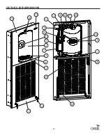
Page 5: ...2 679 24 27 32 631 WASTE DRAIN HEIGHT 4 5 16 110 21 7 32 539 FRAME 3 1 2 89 2 5 32 55 8 1 16 205 3 1 16 78 1 1 2 38 5 16 8 DIA MOUNTING HOLES 4 TOP AND 4 BOTTOM NOTES RECOMMENDED ADULT HEIGHT INTALLAT...

Page 6: ...ELECTRICAL CONNECTIONS 5 16 8 DIA MOUNTING HOLES 8 TOP AND 8 BOTTOM 3 1 16 78 8 1 16 205 1 1 2 38 ELECTRICAL CONNECTIONS 5 11 32 136 3 1 2 89 9 7 8 251 ELECTRICAL OUTLET OPTIMUM LOCATION SEE NOTE 4 13...

Page 7: ...IF APPLICABLE VERSAFILTER III NOTES RECOMMENDED ADULT HEIGHT INSTALLATION SHOWN ADJUST VERTICAL DIMENSIONS AS REQUIRED TO COMPLY WITH FEDERAL STATE AND LOCAL CODES STOP VALVE TRAP PIPE CONNECTOR TO W...

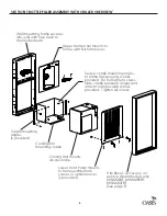
Page 8: ...adle mounting angles 2 provided Cooling Unit mounts inside cradle Lower Front Panel mounts to frame with bottom screws or optional locks 2 provided Trim Bezel accessory on surface mount models only MW...

Page 9: ...instructions on page 11 before continuing with step 1B Place drip tray in frame but do NOT fasten in place Do NOT place grille on tray until last step Section 6 Install snap bushings Install provided...

Page 10: ...d Tube Connections to Filler Fitting Strainer Inside A B C D Attach cradle to frame per rough in drawing Screws Provided 4 Place chiller in frame Install 1 4 union fittings on chiller inlet and outlet...

Page 11: ...o round shape as needed before connecting Attach remaining tubing from ball valve to chiller inlet Remove reducer fitting and copper tube from fountain water line Install provided 1 4 union Determine...

Page 12: ...ce drip tray in frame but do NOT fasten in place Do NOT place grille on tray at this time Install Snap Bushing and any other accessories included Uncoil EBF push button wire lead and route through sam...

Page 13: ...ly power to the junction box and chiller if used Check the electric current available Type and voltage must be the same as listed on the product data plate As you put the bottle filler panel assembly...

Page 14: ...or 3 seconds to reset Gallon or Liter count or momentarily press to advance to next menu FILT CAPAC OF 4750 GAL 18000 LTR Depress button for 3 seconds to change filter capacity to 1250 GAL 5000 LTR fo...

Page 15: ...15 SECTION 8 PARTS BREAKDOWN 1 2 8 3 4 6 5 7 9 10 15 16 18 24 20 21 17 11 12 13 19 23 14 25 26 27...

Page 16: ...SBF LOWER LOUVER 027697 005 1 12 LOCK ASSY 031657 006 2 13 POWER SUPPLY 12VDC 038036 003 1 14 PCB IR SENSOR 042065 001 1 15 LENS PWEBF LCD 042575 001 1 16 SPOUT 042369 001 1 17 LEAD WIRE ASSY 10FR BLA...

Page 17: ...17...

Page 18: ...iew Blvd Columbus OH 43235 Modular Series Electronic Bottle Fillers www oasiscoolers com 1 800 646 2747 OASIS is a registered trademark of LVD Acquisition LLC dba Oasis International 2022 LVD Acquisit...

Reviews: