


2
OASIS AQUA POINTE® ELECTRONIC BOTTLE FILLERS INSTRUCTIONS
1. INSPECTION
Inspect the cartons and various components for evidence of rough handling and concealed damage.
Damage claims should be filed with the carrier.
2. INSTALLATION, PLUMBING & ELECTRICAL CONNECTIONS
a)
Note: The following states require a licensed plumber to install cooler; AR, GA, MA, MI, OK, RI, SC,
SD, TX, VT and WI. CA, KS, MN, NM and OR allow for a state-registered installer or contractor as well. State
and local plumbing codes may prohibit the use of saddle tapping valves for water line connection in some
applications. All connections must conform to applicable plumbing codes.
b)
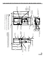
Plumbing rough-in and wall opening should be prepared as shown on roughing-in drawing. This
drinking water cooler is designed to be operated at a water supply line pressure of up to 100 psi (690 kPa).
A pressure regulator must be installed in front of the unit’s water inlet if the pressure (including any possible
pressure spikes) could exceed 100 psi (690 kPa).
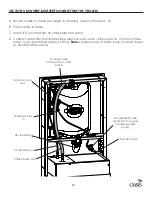
c)
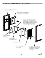
Insert frame assembly into wall opening and secure to studs. NOTE: FRONT FLANGE OF FRAME(S)
MUST BE FLUSH WITH THE FINISHED WALL SURFACE.
d)
Install drain receptor to frame with screws provided.
e)
A 2X4 junction box is provided for the installation of a 115 volt receptacle. The bottle filler is provided
with a power cord with a grounded NEMA 15 plug. This unit is intended to be connected to a ground fault
circuit interrupting (GFCI) device to meet UL requirements. It is recommended that flexible conduit be used to
supply power to the junction box and chiller if used. Check the electric current available. Type and voltage
must be the same as listed on the unit data plate.
f)
As the bottle filler panel assembly is being placed on the frame assembly, feed the long green
ground wire and the terminals on the power supply cord through the bushings in the frame assembly.
g)
Attach the long green ground wire to the frame assembly junction box ground, then plug in bottle
filler power cord.
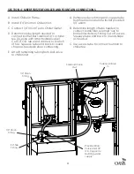
h)
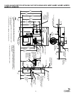
Refer to the appropriate connection diagram for water and drain connections. Check for leaks.
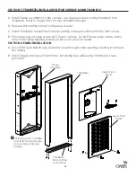
i)
The lower panel can be secured with the provided key locks or screws. The M8EBF features one
lockable and one non lockable lower panel; these are interchangeable.
MODELS WITH CHILLER
j)
Attach cradle mounting angles to unit mounting cradle with 4 screws provided. Slide unit mounting
cradle into frame and secure in place with 4 screws, provided. (Cradle is used only when cooling unit is to be
installed). NOTE: BOTTOM FLANGE ON CRADLE IS TO BE BEHIND FRAME FRONT FLANGE.
k)
Slide cooling unit onto cradle.
M8EBF & M12EBF WITH FOUNTAIN
l)
Install the fountain mounting plate to the frame assembly using the provided screws.
m)
Place the upper panel in place on the frame top angle and fasten with 2 screws, provided, at the
bottom.
n)
Remove the bottom plate from the fountain arm. Save the screws.
o)
Snap the reveal gasket over the back end of the fountain arm.
p)
Add compression connector, furnished by others, to the fountain waste tube and slide back
approximately 3” out of the way. Refer to the appropriate connection diagram.
q)
Hang the fountain on the mounting plate studs. NOTE: AS THE FOUNTAIN IS HUNG, FEED THE WASTE
TUBE INTO THE WASTE STUB ON THE WALL SIDE.
r)
Tighten the fountain to the mounting plate with the 5/16-18 nuts and washers and the 1/4-20 bolts
and washers provided.
s)
Slide the reveal gasket(s) back into the notch between the panel and the arm. The gasket serves as
an appearance item only (to close up any opening around the panel and the mounting plate).
Summary of Contents for Modular Series
Page 17: ...17...