background image

-  English  -

5

4

Questions, problems, missing parts? 

Before returning to your retailer, call us at 1-866-627-3435, 8 a.m.-6 p.m., EST, Monday-Friday, or email 

us at [email protected].  Or visit our website at www.oase-livingwater.com

1.

Maintenance and cleaning

Attention! Dangerous electrical voltage

.

Possible consequences: 

Death or serious injuries.

Protective measures:

•  Electrical units and installations with a rated voltage of U > 12 V AC or U >30 V DC located in the water: Isolate the 

units and installations (switch off and disconnect from the power supply) before reaching into the water.

•  Isolate the unit before starting any work.

•  Secure the unit to prevent unintentional switching on.

WARNING 

This pump uses a very strong magnet to achieve superior performance. When removing the impeller assembly there 

will be considerable magnetic force resisting the extraction of the impeller assembly. This is normal. Likewise when 

replacing the impeller assembly there will be a strong magnetic force pulling the assembly into the pump to potentially 

cause injury to fingers and in rare cases damaging the ceramic shaft or rear bearing. Use thick gloves when replacing 

the impeller assembly.  

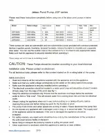
Cleaning the unit


Regular cleaning of the pump may be necessary depending

upon the environment in which it is operated. Clean the pump

when it is visibly soiled or when a drop in performance is

detected. Clean the unit with warm water using a soft brush.


Never use aggressive cleaning agents or chemical solutions. 

These could attack the housing surface or impair the function.


In the event of stubborn furring (calcium deposits), a common 

household cleaner free from vinegar and chlorine can be used. 

Subsequently, clean the pump thoroughly using warm water.

Cleaning the pump

1.


Disconnect the pump from the power source.

○ Disconnect the tubing.

2.


Remove the screen and disassemble the impeller 

housing to expose the impeller assembly.  

3.

   For Pond Pump 280 / 420, remove the impeller 

assembly by gently pulling on the impeller blades.

For Pond Pump 575 remove the impeller assembly by 

pulling on the back round plate behind the impeller.

4. 

  Use a soft cloth or brush to clean the impeller assembly 

and the inside of the impeller housing.


Check parts for damages such as cracked rotor, shaft or 

bearing, cracks in the magnet, and broken plastics. 

Replace parts if necessary.

5.

   Reassemble in the reverse order.

2.

3.

4.

!

280 / 420

575

Summary of Contents for 280

Page 1: ...Pond Pump 280 420 575 Operating instructions Notice d emploi Instrucciones de uso...

Page 2: ...oduct Pond Pump 280 420 575 Prior to operating the unit please read the instructions of use carefully and fully familiarize yourself with the unit Ensure that all work on and with this unit is only ca...

Page 3: ...tant information for trouble free operation Intended use Pond Pump 280 420 575 referred to in the following as unit may only be used as specified in the following For circulating and pumping normal po...
Page 4: ...the water level at regular intervals Always place the unit below water level Attention The installed temperature sensor automatically turns the pump off if it is overloaded The pump automatically swit...

Page 5: ...he ceramic shaft or rear bearing Use thick gloves when replacing the impeller assembly Cleaning the unit Regular cleaning of the pump may be necessary depending upon the environment in which it is ope...

Page 6: ...earings are not broken Pump is not completely submerged Completely submerge pump in the water Insufficient flow Flow control closed too far Adjust flow control Screen clogged Clean Tubing blocked Clea...

Page 7: ...head height cord length connection for hoses Dimensions 280 45418 120V 60 Hz 0 45 A 27 W 280 GPH 7 8 ft 16 ft 3 4 5 82 x 4 x 6 41 in 420 45419 0 8 A 42 W 420 GPH 11 5 ft 575 45420 1 2 A 68 W 575 GPH...

Page 8: ...English Pos Pond Pump 575 1 Pump screen 2 Impeller housing 3 Impeller assembly 4 O ring 5 3 4 in ID tubing adapter with flow control 1 2 3 4 5 8...

Page 9: ...3435 AVANT DE RETOURNER AU MAGASIN Informations sur le mode d emploi Bienvenue OASE Living Water L achat de votre pompe de bassin 280 420 575 constitue un excellent choix Avant d utiliser la pompe lis...
Page 10: ...t comme indiqu dans les points suivants Pour la circulation et le pompage de l eau d un bassin normal pour les filtres et les pi ces d eau additionnelles Fonctionnement en respect avec les donn es tec...

Page 11: ...que de d charge lectrique Cette pompe est fournie avec un conducteur de terre et une fiche de terre Afin de r duire le risque de d charge lectrique assurez vous qu elle est uniquement connect e une pr...

Page 12: ...fiche de la prise lectrique avant de p n trer dans l eau Isolez l appareil avant d y effectuer tout travail S curisez l appareil dans le but d emp cher une mise en marche involontaire AVERTISSEMENT Ce...

Page 13: ...exposer le rotor Tournez le rotor pour vous assurer qu il n est pas bris ou bouch par des d bris De plus assurez vous que l arbre de c ramique ou les roulements ne sont pas bris s La pompe n est pas c...

Page 14: ...5 m 19 mm 148 x 101 6 x 163 mm 420 45419 0 8 A 42 W 1590 LPH 3 5 m 575 45420 1 2 A 68 W 2176 LPH 4 1 m 148 x 101 6 x 165 mm pompe de bassin Pos pompe de bassin 280 420 1 Couvercle Couvercle 2 Bo tier...

Page 15: ...h heure de l Est ou encore envoyez nous un courriel l adresse customercare oase livingwater com Vous pouvez aussi consulter notre site web au www oase livingwater com Pos pompe de bassin 575 1 Couver...
Page 16: ...producto de Estanque Bomba 280 420 575 Antes de poner la unidad en operaci n por favor lea las instrucciones de uso cuidadosamente y completamente para conocer la unidad Aseg rese que cualquier trabaj...

Page 17: ...cable de corriente est da ado antes de instalar y mantener la unidad No remover la clavija de puesta a tierra del enchufe del cable el ctrico Uso diferente del uso previsto Esta unidad puede ser pelig...

Page 18: ...vel de agua regularmente Siempre coloque la bomba debajo del nivel de agua Atenci n El sensor de temperatura instalado apaga la bomba autom ticamente si se sobrecarga La bomba se prende autom ticament...

Page 19: ...iento En el caso de incrustaciones de sarro persistentes dep sitos de calcio puede usar un producto de limpieza de hogar com n libre de vinagre y cloro Luego limpie la bomba cuidadosamente con agua li...

Page 20: ...jamiento del impulsor Reduzca la temperatura del ambiente p ej aseg rese que est cumpliendo con las especificaciones de la temperatura del agua evite la exposici n a la luz del sol directa Impulsor de...

Page 21: ...olumna de agua Longitud de cable Conexiones para tuber a Dimensiones 280 45418 120V 60 Hz 0 45 A 27 W 1060 LPH 2 4 m 5 m 19 mm 148 x 101 6 x 163 mm 420 45419 0 8 A 42 W 1590 LPH 3 5 m 575 45420 1 2 A...

Page 22: ...Espa ol 22 Pos Estanque Bomba 575 1 Pantalla 2 Alojamiento del impulsor 3 Montaje del impulsor 4 Junta T rica 5 Adaptador de tuber a DI con control de flujo 19 mm 1 2 3 4 5...

Page 23: ...OASE North America INC www oase livingwater com 46615 09 16...

Reviews: