background image

6

There are two methods of installing the engine in the aircraft: 
(a)  standard  beam  mounting,  using  the  engine's  integral 
crankcase  mounting  lugs,  and  (b)  radial  mounting,  using  the 
backplate  mount  supplied,  to  bolt  the  engine  to  the  front 
bulkhead or firewall. Whichever method is chosen, make sure 
that  the  structure  to  which  the  engine  is  attached  (i.e. 
horizontal  bearers  or  vertical  bulkhead),  is  of  sturdy 
proportions and very firmly integrated with the airframe. This 
is  necessary  both  for  safety  and  for  the  realisation  of 
maximum performance.  

INSTALLATION

Beam mounting

Use heavy, rigid, hardwood bearers or a metal mount and 
keep  unsupported  length  as  short  as  possible  to  reduce 
frontal overhang.

Make  sure  that  the  bearers  are  parallel  and  that  their 
mounting surfaces are in the same plane.

Use  5mm  or  10-24  steel  cap-head  screws,  such  as  Allen 
hexagon socket type, with locknuts, for bolting the engine 
to the bearers.

Radial mounting

Draw vertical and horizontal centre lines on the firewall to 
correspond with the required thrust-line. Use these to find 
the  centre  of  the  100mm  (3.93  in.)  diameter  bolt-circle 
required to correctly locate the backplate mount.

Depending  on  whether  the  engine  is  to  be  installed  with 
the cylinder upright, inverted, angled or horizontal, position 
the backplate mount so that the access hole in the side of 
the  mount  is  conveniently  located  to  receive  the  fuel  line 
and  muffler-pressure  line  from  tank  to  engine.  Place  the 
mount  against  the  firewall  so  that  its  six  mounting  holes 
are accurately aligned on the bolt ciircle. Mark off the bolt-
hole centers and drill six 6.5mm holes through the firewall.
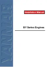
Remove  the  crankcase  cover  plate  from  the  engine. 
Carefully slide the O-ring seal from the cover plate and fit 
it, to the retaining groove on the backplate mount.

Fit  the  backplate  mount  to  the  engine  in  the  required 
position  and  secure  it  firmly  with  the  four  M5x22  Allen 
screwa provided.
Bolt  the  complete  engine  and  backplate  mount  assembly 
to  the  firewall,  using  the  six  M5x25  Allen  screws,  toothed 
lock washers and blind nuts supplied.

Firewall

Toothed lock washer

M5x25

O-ring

Backplate mount

At least 15mm rigid
hard plywood

M5 Blind nut

6.5mm hole

M5x22

100mm

7

Before  connecting  the  throttle-lever / servo  linkage,  make 
sure that no part of the linkage interferes with the internal 
structure  of  the  aircraft  or  wiring,  etc.,  when  the  throttle  is 
fully open or fully closed.
Set the throttle lever linkage so that the throttle rotor is (a) 
fully  open  when  the  transmitter  throttle  stick  is  fully 
advanced and  (b) fully closed when the throttle stick is fully 
retarded.  Adjustment  of  the  throttle  rotor  opening  at  the 
idling position can then be made with the throttle trim lever 
on  the  transmitter.  (Select  throttle-lever  and  servo-horn 
hole  positions  that  will  avoid  excessive  pushrod  travel 
causing the throttle to bind at either end.)

THROTTLE LINKAGE

When  adjusting  the  throttle  lever  angle,  relative  to  the 
rotor,hold  the  rotor  at  about  half-way  between  the  open 
and  closed  positions  while  loosening  and  tightening  the 
fixing  screw,  otherwise  the  rotor,  rotor  guide 
screw,throttle  stop  screw  or  carburetor  body  may 
become burred and damaged.

Note: 

INSTALLATION OF SILENCER(MUFFLER)

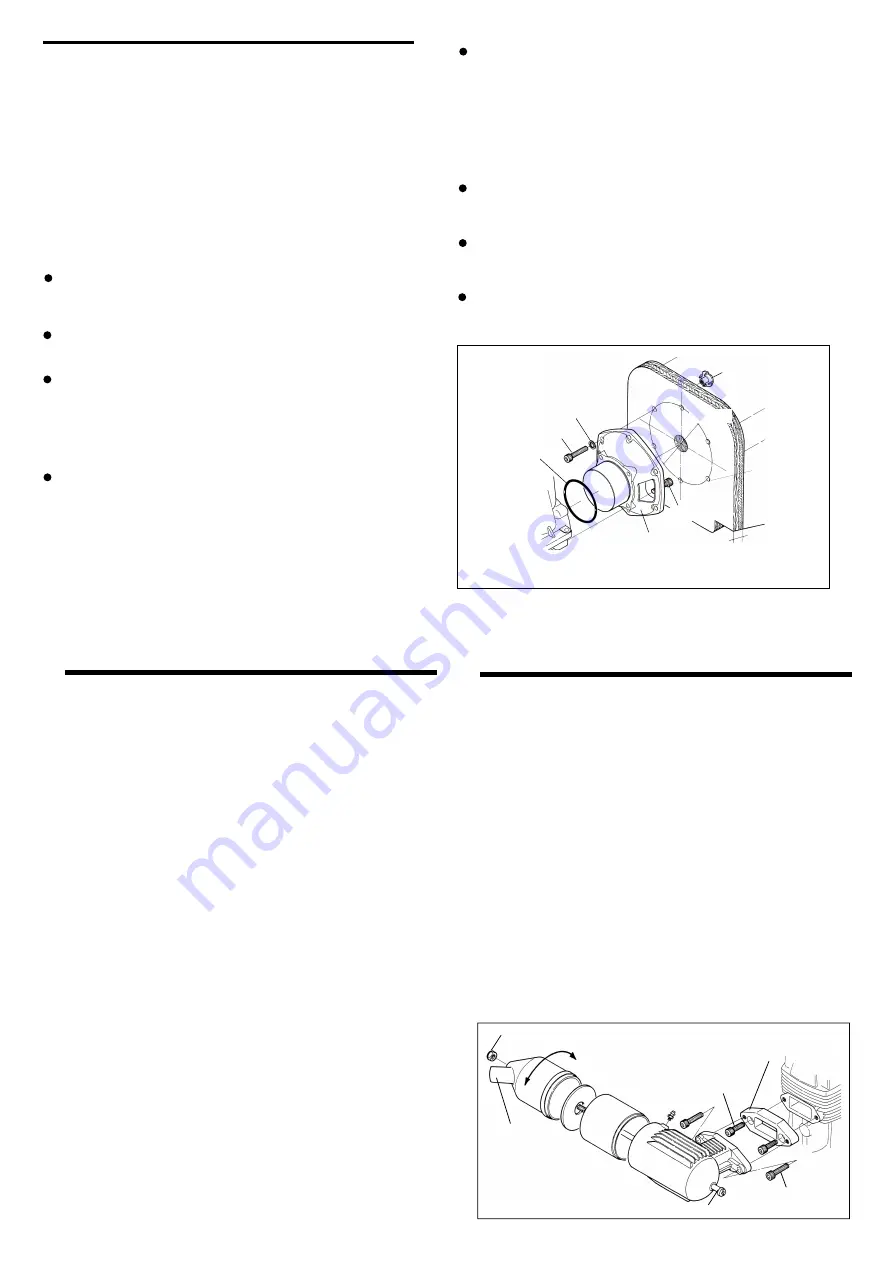
To fit the standard silencer

Fix the exhaust adaptor plate to the engine with the two M5 
x15 Allen screws supplied.

1.

Now  fit  the  silencer  to  the  exhaust  adaptor  with  M5x20 
Allen screws, also provided.

2.

In  order  to  prevent  the  leakage  of  exhaust  oil  from 
between  the  engine  and  adaptor,  and  between  the 
adaptor and silencer, apply a suitable silicone sealant to 
the joint faces during assembly.

NOTE:

The angled exhaust outlet is agjustable and can be rotated to 
any desired position in the following manner.

Loosen locknut and assembly screw.
Set the exhaust outlet at the required angle by rotating the 
rear part of the silencer.
Re-tighten the assembly screw, followed by the locknut.

1.

2.

3.

M5x15

M5x20

Lock nut

Exhaust Outlet

Turn to required position

Exhaust adaptor

Assembly screw

Summary of Contents for Max-BGX-1 Ring

Page 1: ...aircraft radio control equipment etc are accessible for checking at the same time 1 CONTENTS 15 SAFETY INSTRUCTIONS AND WARNINGS ABOUT YOUR O S ENGINE INTRODUCTION BASIC ENGINE PARTS INSTALLATION THROTTLE LINKAGE INSTALLATION OF SILENCER MUFFLER FUEL TANK LOCATION GLOWPLUGS FUEL PROPELLER MIXTURE CONTROLS STARTING RUNNING IN Breaking in MIXTURE CONTROL ADJUSTMENT CHART SUBSEQUENT READJUSTMENT CARB...

Page 2: ...your engine in an enclosed space Model engines like automobile engines exhaust deadly carbon monoxide Run your engine only in an open area Model engines generate considerable heat Do not touch any part of your engine until it has cooled Contact with the muffler silencer cylinder head or exhaust header pipe in particular may result in a serious burn 3 NOTES This engine was designed for model aircra...

Page 3: ...diately after a glowplug ignition engine has been run and is still warm conditions sometimes exist whereby it is just possible for the engine to abruptly restart if the propeller is casually flipped over compression WITHOUT the glowplug battery being reconnected Remember this if you wish to avoid the risk of a painfully rapped knuckle NOTES 5 INTRODUCTION INSTALLING THE GLOW PLUG Glow plug Careful...

Page 4: ...2 Allen screwa provided Bolt the complete engine and backplate mount assembly to the firewall using the six M5x25 Allen screws toothed lock washers and blind nuts supplied Firewall Toothed lock washer M5x25 O ring Backplate mount At least 15mm rigid hard plywood M5 Blind nut 6 5mm hole M5x22 100mm 7 Before connecting the throttle lever servo linkage make sure that no part of the linkage interferes...

Page 5: ...Starting qualities deteriorate 9 FUEL Model engine fuel is poisonous Do not allow it to come into contact with the eyes or mouth Always store it in a clearly marked container and out of the reach of children Model engine fuel is also highly flammable Keep it away from open flame excessive heat sources of sparks or anything else which might ignite it Do not smoke or allow anyone else to smoke near ...

Page 6: ... the first few times known as running in or breaking in This is because the working parts of a new engine take some time to settle down after being subjected to high temperatures and stresses Therefore it is vitally important to complete the break in before allowing the engine to run continuously at high speed and before finalizing carburettor adjustments However because O S engines are produced w...

Page 7: ...dle valve settings i e ignition of the fuel charge takes place at every fourth stroke of the piston instead of at every second stroke 1 2 3 4 5 6 7 13 MIXTURE CONTROL ADJUSTMENT CHART Start the engine Make sure that the throttle is fully open Adjust the neede valve Close the throttle gradually Find the idling position Fix the idling position Open the throttle fully Does the engine regain full powe...

Page 8: ...O S Super Filters large and small are available as optional extras to deal with this problem One of these filters fitted to the outlet tube inside your refueling container will prevent the entry of foreign material into the fuel tank It is also recommended that a good in line filter be installed between the tank and needle valve Do not forget to clean the filters regularly to remove dirt and lint ...

Page 9: ...00 29308000 29208200 29320000 46231000 29301000 71704230 28282000 28281970 24981837 26381501 26711305 46181950 29330000 29302000 29314010 29307000 29313000 71919000 71608001 29325000 29325300 29325400 29326000 The specifications are subject to alteration for improvement without notice C M4x20 N M5x15 C M5x10 S M3x3 1 2 3 4 5 6 7 8 9 10 10 1 11 12 13 14 15 15 1 15 2 15 3 15 4 15 5 16 17 18 19 20 17...

Page 10: ...3 8 M5 S GLOWPLUG 71608001 No 8 A5 71605100 SILICONE TUBE ASSEMBLY 72102300 EXHAUST HEADER PIPE 72102200 T 6000 TUNED SILENCER 72102010 55500004 M5 79870050 M5 72200080 NEEDLE VALVE EXTENSION CABLE SET The specifications are subject to alteration for improvement without notice 19 Dimensions mm Specifications THREE VIEW DRAWING Displacement Bore Stroke Practical R P M Output Weight 34 97 cc 2 13 cu...

Page 11: ...served Printed in Japan TEL 06 6702 0225 FAX 06 6704 2722 6 15 3 Chome Imagawa Higashisumiyoshi ku Osaka 546 0003 Japan 60090440 061102 URL http www os engines co jp U N E Q U A LLED QUALITY PRECISION PERFOR M A N C E E S T A BLISHING THE STANDARDS OF EXCELLE N C E ...

Reviews: