background image

WARNING

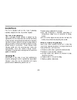
When checking the plug with energizing it,

hold the plug with tools, such as pliers, etc.
Do not bring your face close to the plug or

the boiled fuel remaining in the filament will
burn you.

3. Check that the current to the glowplug is

switched off.

4. To close the needle-valve, turn it

clockwise, while to open the

needle-valve, turn it counter-

clockwise. Turn the needle-valve
clockwise slowly until it stops.

This is the fully closed position.

Fully opened

Open

5.0pen the needle-valve 2-2.5

turns from the fully closed

position and set the throttle in

the fully open position.

position

6. Apply the starter and press the starter switch

for 5-6 seconds to prime the engine.

7. Position the throttle stick at 2-3 scales

advanced from the fully pulled down position.

Turn the prop "backwards" (clockwise) by
hand until it is arrested by compression. This
is to enable the kinetic energy of the prop to
subsequently assist the starter through the

compression stroke to  start the engine.

Glow Plug Igniter

Replace the plug when the
element does not glow or is

burnt out.

Pliers

Element glows when energized.

Close

Close

26

Summary of Contents for FL-70

Page 1: ...ly adhere to the advice contained therein Also please study the entire contents of this instruction manual so as to familiarize yourself with the controls and other features of the engine Keep these instructions in a safe place so that you may readily refer to them whenever necessary It is suggested that any instructions supplied with the aircraft radio control equipment etc are accessible for che...

Page 2: ...INES 18 20 THROTTLE LINKAGE NEEDLE VALVE EXTENSION 21 PROPELLER SPINNER ATTACHMENT 22 23 GLOWPLUG 24 TYPE 60W CARBURETOR STARTING 25 27 RUNNING IN CARBURETOR 27 30 CARBURETOR AIR BLEED ADJUSTMENT 31 TROUBLE SHOOTING WHEN THE ENGINE FAILS TO START 32 33 VALVE ADJUSTING 34 HOW TO SET THE CAMSHAFT TIMING 35 CARE AND MAINTENANCE 36 37 ENGINEEXPLODEDVIEWS PARTSLIST 38 39 CARBURETOR EXPLODED VIEWS PARTS...

Page 3: ...e date your O S engine is acquired by another person we would respectfully request that these instructions are also passed on to its new owner The advice which follows is grouped under two headings according to the degree of damage or danger which might arise through misuse or neglect WARNINGS These cover events which might involve serious in extreme circumstances even fatal injury NOTES These cov...

Page 4: ...afety Never touch or allow any object to come into contact with the rotating propeller and do not crouch over the engine when it is running Never operate your engine in an en closed space Model engines like auto mobile engines exhaust deadly carbon monoxide Run your engine only in an open area Model engines generate considerable heat Do not touch any part of your engine until it has cooled Contact...

Page 5: ...aring Such noise is also likely to cause annoyance to others over a wide area If you remove the glowplug from the engine and check its condition by connecting the battery leads to it do not hold the plug with bare fingers Use an appropriate tool or a folded piece of cloth Install a top quality propeller of the diameter and pitch specified for the engine and aircraft Locate the propeller on the sha...

Page 6: ...them Preferably use an electric starter The wearing of safety glasses is also strongly recommended Discard any propeller which has become split cracked nicked or otherwise rendered unsafe Never attempt to repair such a propeller destroy it Do not modify a propeller in anyway unless you are highly experienced in tuning propellers for specialized competition work such as pylon racing Take care that ...

Page 7: ... sand The propeller may throw such material in your face and eyes and cause injury For their safety keep all onlookers especially small children well back at least 20 feet or 6 meters when preparing your model for flight If you have to carry the model to the take off point with the engine running be especially cautious Keep the propeller pointed away from you and walk well clear of spectators Warn...

Page 8: ... when the engine is cold This is normal The cylinder bore Is a little tapered The piston and cylinder are designed to achieve a perfect running clearance when they reach their running temperatures When the engine is cold When the engine is hot Crankshaft A little tapered Piston Cylinder Liner ...

Page 9: ...is could cause hydraulic lock and damage the engine on application of the electric starter If over primed remove glowplug close needle valve and apply starter to pump out surplus fuel Cover the head with waste to prevent pumped out fuel coming into your eyes 8 ...

Page 10: ...ssembly Also a sealed front bearing prevents oil leaks The engine is fitted with the new easy to use O S 60W airbleed carburetor This engine is designed so that more R 0 pilots from hobby beginners to skilled Sunday fliers may enjoy the performance advantages of four stroke engines greater fuel economy higher torque lower noise and realistic sund STANDARD ACCESSOIES Glow Plug Type F fitted with th...

Page 11: ...bility and power The carburetor is adjusted at the factory for a fuel containing 20 lubricant and 15 nitromethane Some commercial fuels also contain coloring additives as an aid to fuel level visibility In some cases these additives have indicated slightly negative effects o performance We would suggest that you use such fuels only if you are satisfied that they do not adversely affect running qua...

Page 12: ...ling container to prevent entry of foreign matter into fuel tank O S Super Filters large and small are available as optional extras O S Non Bubble Weight To prevent the pickup from adhering to the tank wall under suction and restricting fuel flow slots may be filed I the end of the weight Alternatively O S Non Bubble Weight is available as an optional extra Fuel Filter It is recommended to fit a g...

Page 13: ...er to the props listed in the accompanying table Slightly larger or even slightly smaller props than those shown in the table may be used but remember that the propeller noise will increase if blade tip is raised due to higher rpm or if a larger diameter lower pitched prop is used Sport Aerobatic Trainer Scale 12X7 12 5X6 13X6 12 5X6 13X6 7 Warning Make sure that the propeller is well balanced An ...

Page 14: ...IP Recommended for easy removal and replacement of the angled and recessed glowplug the O S Long Socket Wrench incorporates a special grip Plus Threaded Drivers No 1 No 2 etc 8mm Spanners 8mm 13mm 14mm etc SCREWDRIVER Necessary for carburetor adjustments No 1 No 2 etc Box Wrenches 5 5mm 7mm 8mm opposite side 13 Nipper ...

Page 15: ...mbly Exhaust Header Pipe Nipple No 1 Larger hole Nipple No 5 Smaller hole Lock Nut Propeller Washer Cover Plate Rotor Guide Screw Throttle Lever Airbleed Screw Glow Plug Lock Nut Set Drive Hub Beam Mount Crankcase Carburetor Type 60W Silencer Body Needle ...

Page 16: ...hould be of rigid hardwood and of at least 15mm or 5 8 in square section Make sure that the mounting beams are parallel and that their top surfaces are in the same plane Front view Side view Top surfaces are in the same plane Oppositebeam Top surfaces are not in the same plane Engine does not rest firmly Re align the surfaces as necessary Top surfacesare not in the same plane INCORRECT CORRECT 15 ...

Page 17: ... structure to absorb vibration Use 3mm or larger steel screws preferably Allen type hexagon socket head cap screws with washers and locknuts for bolting the engine to the bearers INSTALLINGTHEGLOWPLUG Install washer on glowplug and insert carefully into cylinder head making sure that it is not cross threaded before tightening firmly Glow plug Washer 3mm steel nuts Tighten second nut firmlydown ont...

Page 18: ...her locknut The application of a heatproof silicone sealant to the threads of the exhaust system is recommended to reduce the risk of joints loosening and the leakage of exhaust gasses and oil residue Reminder Model engines generate considerable heat and contact with the header pipe or silencer may result in a serious burn If you need to tighten the silencer joints which may loosen when they are h...

Page 19: ...idling r p m a little higher to prevent engine cutting Piping suitable for acrobatic flights With the general piping the fuel in the tank may flow into the silencer when the throttle is set to slow during upside down flight or vertical dive which may result in engine stop due to mixture change at low speed Piping shown in the Fig 2 prevents fuel flowing into the silencer and engine stop at slow ru...

Page 20: ...ilicone Tubing Do not use wire cutter or pliers If you should need to clean out silicone tubes use methanol or glow fuel not gasoline or kerosene No 1 Nipple larger hole Fuel Fitter commercially available Fuel Stopper commercially available Carburetor Center Line Fuel Tank Center Line Approx 10mm Refueling tubing T Nipple supplied 19 ...

Page 21: ...nstall the fuel tank so that carburetor center line and fuel tank center line may come to as much close as possible T Nipple supplied Fuel Filter commercially available Fuel Stopper commercially available Refueling tubing T Nipple commercially available Approx 10mm Plug commercially available 20 ...

Page 22: ...hrottle arm and servo horn so that they move symmetrically and smoothly through their full travel NEEDLE VALVE EXTENSION The needle valve supplied with this engine is designed to incorporate an extension so that when the engine is enclosed within the fuselage the needle valve may be adjusted from the outside Cut a commercially available rod to the required length bend one end to an L shape insert ...

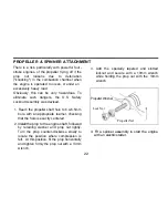
Page 23: ...t hole to 6 4 6 5mm bore with an appropriate reamer checking that the hole is exactly centered 2 Install the prop to the engine shaft followed by retaining washer and prop nut lightly Turn the prop counter clockwise slowly to locate the position where compression is felt At this position fit the prop horizontally and tighten firmly the prop nut with a 13mm wrench 3 Add the specially tapered and sl...

Page 24: ...for Spinner Code No 45810200 and Propeller Locknut Set for Tru Turn Spinner Code No 145810300 IMPORTANT Regardless of the type of propeller fixing used make a habit of always checking the tightness of the propeller before starting the engine Remember that especially with wooden propellers there is a tendency for the material to shrink or for it to be reduced by the serrated face of the drive hub 2...

Page 25: ...d Glowplug life Particularly in the case of very high performance engines glowplugs must be regarded as expendable However plug life can be extended and engine performance maintained by careful use i e Install a plug suitable for the engine Use fuel containing a moderate percentage of nitromethane unless more is essential for racing events Do not run the engine too lean and do not leave the batter...

Page 26: ... adjusted is explained in the succeeding sections under Starting Running in and Idling Adjustment STARTING The FL 70 is not equipped with manual choke controls as it is intended for use with an electric starter only A high torque electric starter not only makes starting the engine easier it dispenses with the need for a choke valve by turning the engine over fast enough to cause the fuel pump to p...

Page 27: ...ned Open 5 0pen the needle valve 2 2 5 turns from the fully closed position and set the throttle in the fully open position position 6 Apply the starter and press the starter switch for 5 6 seconds to prime the engine 7 Position the throttle stick at 2 3 scales advanced from the fully pulled down position Turn the prop backwards clockwise by hand until it is arrested by compression This is to enab...

Page 28: ...r are fully pulled down Close RUNNING IN Breaking in For long life and peak performance every engine needs special treatment when new know as running in or breaking in This is a procedure during which the engine is operated under strictly controlled conditions at the beginning of its life in order to avoid the risk of immediate damage to certain components through becoming overheated or stressed a...

Page 29: ...mixture so induced will cool the engine at the same time providing increased lubrication 5 Repeat this process alternately running the engine fast and slow by means of the needle valve while keeping the throttle fully open then begin to extend the short periods of high speed operation until two tanks of fuel have been consumed WARNING When ground running the engine avoid dusty or sandy locations I...

Page 30: ...e equipped with a throttle type car buretor which provides a wide range of engine speed control With the throttle lever linked to a suitable servo in the model movement of the throttle control on the transmitter will enable engine to be varied proportionally from idling speed to full power The carburetor of your engine has been factory set for the approximate best results and no adjustment except ...

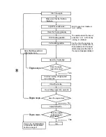
Page 31: ...e is fullyopen Adjusttheneede valve Close the throttle gradually Find the idling position Fixtheidlingposition Re settheidlingposition at alittlehigherr p m Open the throttle fully Does the engine regainfullpower Yes Engine stops Continue running at high speed lor 10 seconds Close the throttle Run at idling speed lor 5 seconds Does the engine slop No Engine stops Applyfull throttle Does the engine...

Page 32: ...Stop the engine Note Stop engineby pinching fuel line Do not touch needle vatve These adjuslments can be made without stopping the engine However it is advisablefor beginners to slop the engine for safety reasons approx 15 degrees Immediatety point nose down so that engine runs steadily again Stoptheengine Close air bleed screw Half turn at a time Half turn at a time Open air bleed screw Attention...

Page 33: ... the electric starter battery Glowplug battery Recharge lead acid cell or replace dry battery Note An unused or almost discharged unused dry battery may sometimes be of insufficient capacity if it is old stock Glowplug element Is Replace glowplug Check that applied voltage Is not too high burnedout Something wrong with Check glowplug heating using other leads battery leads Engine flooded due to Cl...

Page 34: ...attery may sometimes be of insufficient capacity it it is old stock Insufficient priming Repeat priming procedure referring to Priming Mixture too rich Close needle valve hall turn 180 and wait for several minutes then re start Priming is not necessary Fuel not reaching the Make sure that tank is filled with fuel Check that there Is not something engine wrong with the fuel line kinked or split Che...

Page 35: ...time has been consumed a loss of power is detected or if he engine has been disassembled for repair these clearances should be checked and reset as necessary For checking and adjusting the valve clearances VALVE ADJUSTING TOOL KIT is available as an optional accessory The kit comes in a plastic case and includes Code No 72200060 Feeler gauge 0 04mm Feeler gauge 0 1 mm Hex key 1 5mm Wrench 5mm 34 ...

Page 36: ...into camshaft housing until it stops Locate mark on the side of camshaft gear in line with the push rod 4 Rotate crankshaft right and left a little and make sure that the mark on the gear is in line with the push rod when the T mark on the drive hub matches the crankcase center line 5 Secure cam cover with screws The relation of position between mark of the gear and teeth may differ from the sketc...

Page 37: ... S are available as optional extra Fit an in line fuel filter between the tank and carburetor to prevent dist and dust in the tank entering the carburetor Clean these filters periodically If these precautions are neglected restriction of fuel flow may cause the engine to cut out or the fuel air mixture to become too lean causing the engine to overheat The use of modern high performance alcohol bas...

Page 38: ...r several times by hand When the engine is not to be used for some months for example as between flying seasons a worthwhile precaution is to remove it from the airframe and after washing off the exterior with alcohol not gasoline nor kerosene remove carefully the carburetor with intake pipe glow plug and all silicone tubing and put them safely aside Then immerse the engine in a container of alcoh...

Page 39: ...ENGINE EXPLODED VIEW Type of screw C Cap Screw B Binding Head Screw M Oval Fillister Head Screw F Flat Head Screw N Round Head Screw S Set Screw ...

Page 40: ...rm 1pc Tappet Adjusting Screw Intake Valve Assembly 1 pair Intake Valve 1pc Valve Spring 1pc Valve Spring Seal 1pc Valve Spring Retainer 2ps Exhaust Valve Assembly 1pair Exhaust Valve 1pc Valve Spring 1pc Valve Spring Seat 1pc Valve Spring Retainer 2ps Cylinder Head W Gasket Cylinder Head W Gasket and Valve Assembly Carburetor Complete 60W Head Gasket Cylinder Piston Assembly Piston Pin Connecting...

Page 41: ...CARBURETOR EXPLODED VIEW Type of screw C Cap Screw B Binding Head Screw M Oval Fillister Head Screw F Flat Head Screw N Round Head Screw S Set Screw 40 ...

Page 42: ... 45281920 22681953 44481310 Description Throttle Lever Assembly Throttle Lever Retaining Screw Carburetor Rotor Carburetor Body Carburetor Rubber Gasket Needle valve Assembly 0 Ring 2pcs Set Screw Nozzle Assembly Ratchet Spring Nozzle Retaining Screw 2pcs Fuel Inlet No 1 Air bleed Screw Specifications are subject to alteration for improvement without notice 41 ...

Page 43: ...n Cable Set _ 72200080 PROPELLER LOCKNUT SET 45810100 45810200 For Spinner PROPELLER LOCKNUT SET FOR TRU TURN SPINNER 1 4 M5 45810300 FLEXIBLE EXHAUST PIPES EXHAUST HEADER PIPES 72109500 72109600 Code No 72108100 72108110 72108120 72108130 Type 1111A HUB 1111C 1111D Length mm 120 240 170 330 Inside Outside 42 TYPEF 71615009 ...

Page 44: ...71521000 VALVE ADJUSTING TOOL LIT 72200060 LOCK WASHER 10sets M3 55500002 BLIND NUT 10pcs sets M3 79870030 CAP SCREW SETS 10pcs sets M2 6x8 79871025 M2 6x10 79871030 M3 5x12 79871080 M3 5x20 79871100 71531000 Thespecificationsaresubjecttoalteration orimprovementwithoutnotice 43 ...

Page 45: ... 090 in 19 0mm 0 748 in 2 300 12 000 r p m 1 1ps 11 000 r p m 467g 16 480Z 51 5g 1 8oz Displacement Bore Stroke Practical R P M Power output Weight Silencer including exhaust header pipe THREE VIEW DRAWING Dimension mm Specification ...

Page 46: ...me Imagawa Higashisumiyoshi ku Osaka 546 0003 Japan TEL 06 6702 0225 FAX 06 6704 2722 URL http www os engines co jp C Copyright 2004 by O S Engines Mfg Co Ltd All rights reserved Printed in Japan 60091500 050400 ...

Reviews: