NXP Semiconductors LPC55S36-EVK User Manual Download Page 43

version number, for example, V2_220). The directory has a "Readme.txt" file and few subdirectories that contain other
package components, including host device drivers, MCU-Link firmware, and scripts to program CMSIS-DAP and J-Link
firmware.
Host drivers are usually installed automatically during firmware package installation. In case you need to install the drivers
manually, refer to the "Host Configuration" section of the "Readme.txt" file.
Before powering up the board for updating MCU-Link firmware, you must switch MCU-Link to ISP mode (USB1).

5. To force MCU-Link to boot in ISP mode (USB1), short jumper JP25.
6. Connect the J1 connector on the board to the USB port of the host computer through a USB micro-B cable. MCU-Link

gets powered up in ISP mode (USB1). The red MCU-Link status LED (D16) lights up (for more details on MCU-Link
LEDs, see 

MCU-Link status LEDs

). The board gets enumerated as a human interface device (HID) class device.

7. Program the MCU-Link firmware into the MCU-Link internal flash using the instructions provided in the "Firmware

Installation Guide" section of the "Readme.txt" file. Use the scripts provided to program the CMSIS-DAP or J-Link
firmware.

8. Disconnect the board from the host computer, remove jumper JP25, and reconnect the board.

Now, the system behaves differently based on whether the CMSIS-DAP or J-Link firmware was programmed:

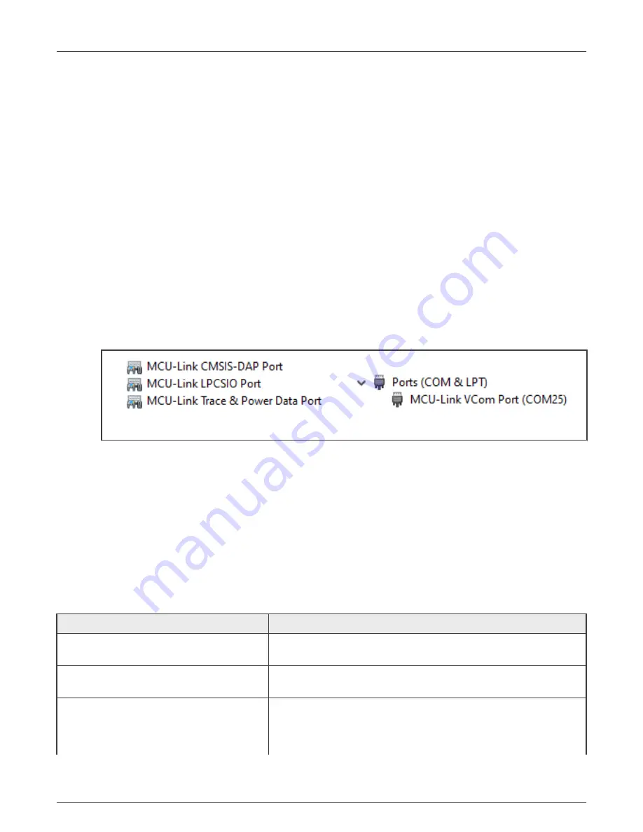
• If the CMSIS-DAP firmware was programmed, then the red status LED (D16) fades in/out repeatedly (“breathing”),

while the green USB status LED (D14) stays ON constantly. In this case, four devices (three HID devices and one
VCOM port) get enumerated, as shown in the figure below.

Figure 15. MCU-Link enumerated devices for CMSIS-DAP firmware

• If the J-Link firmware was programmed, then only the green VCOM LED (D17) is used to indicate status. The VCOM

LED lights up when MCU-Link boots. Then, when you start a new debug session, the LED blinks to indicate that debug
activity is in progress. In this case, two devices (one J-Link driver USB device and one J-Link CDC UART port VCOM
port) get enumerated.

Now, your LPC55S36-EVK board is ready for use. If you use the board with MCUXpresso IDE version 11.3 or higher, you are
notified in case a more recent firmware version is available for MCU-Link. If you use the board with a different IDE, ensure that
latest MCU-Link firmware version is installed on the board.

3.3 Supported MCU-Link features

The table below summarizes the MCU-Link features supported on the LPC55S36-EVK board.

Table 24. Supported MCU-Link features

Feature

Description

Serial wire debug (SWD) / serial wire debug
trace output (SWO)

Allows SWD-based debugging with SWO for profiling and/or low overhead
debug standard I/O communication

Virtual communication (VCOM) serial port

Adds a serial COM port on the host computer, and connects it to the
target MCU by using MCU-Link as a USB-to-UART bridge

USB serial input/output (USBSIO

1

) port

Adds a USB serial I/O port on the host computer, and connects it to the
target MCU by using MCU-Link as a USB-to-SPI bridge or USB-to-I2C
bridge. It also allows MCU-Link to be used as a USB-to-GPIO bridge to
connect the MCU-Link LPC55S69 target to the host computer.

Table continues on the next page...

NXP Semiconductors

MCU-Link Debug Probe

LPC55S36-EVK Board User Manual, Rev. 1, 24 January 2022

User Manual

43 / 49

Summary of Contents for LPC55S36-EVK

Page 1: ...LPC55S36 EVK Board User Manual Supports LPC55S36 EVK Board Revision C NXP Semiconductors Document identifier LPC55S36 EVKUM User Manual Rev 1 24 January 2022...

Page 2: ...S socket 37 2 13 Motor control and Arduino sockets 38 2 13 1 Motor 1 control unused MCU pin socket 38 2 13 2 Motor 2 control Arduino socket 39 2 14 GPIOs and interrupts 40 2 15 Board errata 41 2 16 Bo...

Page 3: ...Appendix A Revision History 48 NXP Semiconductors Contents LPC55S36 EVK Board User Manual Rev 1 24 January 2022 User Manual 3 49...

Page 4: ...g it from the LPC55S69 MCU This document provides detailed information about the LPC55S36 EVK board interfaces power supplies clocks push buttons jumpers and LEDs 1 1 Acronyms and abbreviations The ta...

Page 5: ...only under a non disclosure agreement NDA To request access to these documents contact your local field applications engineer FAE or sales representative Table 2 Related documentation Document Descrip...

Page 6: ...e below shows the LPC55S36 EVK block diagram LPC55S36 LPC5536 CAN FD DB9 Monitor sensor Audio codec User LEDs HS SPI I3C SEC GPIO GPIO PWM COMP Expansion connectors mikroBUS I2C ISP SWD SDO SPI ISP HS...

Page 7: ...ernal UART connection from one of the connectors of mikroBUS socket I2C Flexcomm modules 1 3 and 7 FC1 I2C Supports a USB to I2C bridge between MCU Link and the target MCU FC3 I2C Connects to one of t...

Page 8: ...cepts the following external power supplies External 5 V power through one of the three USB connectors VIN1 power from one of the connectors of the Motor 1 unused MCU pin socket VIN2 power from one of...

Page 9: ...ake up SW3 User SW2 Reset D4 D5 D16 D18 D17 D15 D20 D14 Motor 2 Arduino Motor 2 Arduino Figure 2 LPC55S36 EVK connectors push buttons and LEDs top side view The figure below shows the bottom side view...

Page 10: ...r 1 Figure 3 LPC55S36 EVK connectors and LEDs bottom side view The figure below shows jumpers of the LPC55S36 EVK board NXP Semiconductors LPC55S36 EVK Overview LPC55S36 EVK Board User Manual Rev 1 24...

Page 11: ...are described in the table below Table 5 LPC55S36 EVK connectors Part identifier Connector type Description Reference section J1 USB 2 0 micro B receptacle MCU Link debug probe USB connector USB inte...

Page 12: ...10 2x8 position receptacle J9 2x10 position receptacle J12 2x8 position receptacle J132 2x6 position receptacle Motor 2 control Arduino socket connectors Motor 2 control Arduino socket J102 2x8 positi...

Page 13: ...N2 supply that comes from Motor 1 unused MCU pin socket Motor 2 Arduino socket JP12 1x2 pin header USART connector disable jumper Open UART connection from USART connector JP3 is driven to the target...

Page 14: ...d to disable the USB to SPI bridge so that the target MCU HS SPI port can be used for other purposes for example as a SPI connection from SPI NOR flash memory JP23 1x2 pin header HS CAN transceiver hi...

Page 15: ...I O selection jumper Pins 1 2 shorted Target MCU pin PIO0_2 sends receives input output to from jumper JP61 Pins 2 3 shorted default setting Target MCU pin PIO0_2 sends receives input output to from M...

Page 16: ...mper Pins 1 2 shorted default setting Jumper JP44 pin 1 sends receives serial data to from octal flash memory external flash memory Pins 2 3 shorted Jumper JP44 pin 1 sends receives I2C I2S data analo...

Page 17: ...t MCU pin PIO1_15 sends receives serial data to from octal flash memory external flash memory JP68 1x2 pin header Target MCU pin PIO0_19 output enable jumper Open default setting Target MCU pin PIO0_1...

Page 18: ...e this setting to reprogram the MCU Link internal flash with a new image or use the MCUXpresso IDE with CMSIS DAP protocol By default MCU Link flash is preprogrammed with a version of CMSIS DAP firmwa...

Page 19: ...ting MCU_VDDA power supply is available JP22 1x2 pin header MCU_VBAT supply enable jumper Open MCU_VBAT supply is OFF Shorted default setting MCU_VBAT supply is available JP28 1x2 pin header MCU_MAIN...

Page 20: ...pins 3 4 shorted ISP0 is High and ISP1 is Low Target MCU boots in In System Programming ISP mode JP27 1x2 pin header MCU Link serial wire debug SWD disable jumper Open default setting MCU Link SWD fea...

Page 21: ...data JP52 1x3 pin header Target MCU pin PIO1_25 function control jumper Pins 1 2 shorted Target MCU pin PIO1_25 acts as UART GPIO pin Pins 2 3 shorted default setting Target MCU pin PIO1_25 acts as P...

Page 22: ...in header Target MCU pin PIO0_29 signal selection jumper Pins 1 2 shorted default setting Target MCU pin PIO0_29 communicates to MCU Link USART connector JP3 audio expansion connector Pins 2 3 shorted...

Page 23: ...ower Down mode it comes out of this mode SW2 connects to the target MCU pin RESETN SW3 User button USR The purpose of this button can be defined in user application code It connects to the target MCU...

Page 24: ...ions 2 1 Power supplies The LPC55S36 EVK board is powered up using the following primary power supplies External 5 V power through USB micro B connector J1 External 5 V power through USB micro B conne...

Page 25: ...ctric EXT_USB_5V0 5 V Another source for SYS_5V0 supply Produces HOST_USB_VBUS supply through load switch U7 NX5P3090UK Should be powered when using the target MCU USB0 in Host mode USB connector J3 Z...

Page 26: ...D4 and D5 and voltage translator U11 U4 XC6203E192PR G Torex Semiconductor VCC_1V9 1 9 V at 40 mA max Another source for VCC_3V3_1V9 supply Third power source for audio expansion connector One of the...

Page 27: ...1V9 supply through jumper JP22 MCU_VBAT 3 3 V or 1 9 V Provides VBAT power to the target MCU From MCU_VCC_3V3_1V9 supply through jumper JP28 MCU_MAIN 3 3 V or 1 9 V Provides VDD_MAIN power to the targ...

Page 28: ...USB0 port can work in either Host or Device mode In USB0 Host mode the J2 connector must be used as the power supply source 5 V for the board In USB0 Device mode the J3 connector can serve as a power...

Page 29: ...target MCU can be used for debugging the target MCU from MCU Link Bidirectional voltage translator U11 74AVC4TD245BQ It creates an external UART connection from USART connector JP3 by shifting voltag...

Page 30: ...55S36 EVK board the I2C module is accessed using Flexcomm modules 1 3 and 7 of the target MCU The figure below shows the I2C diagram of the LPC55S36 EVK board LPC5536 MCU Link Voltage translator Motor...

Page 31: ...vity to audio line in line out connectors J5 and J6 I2C address is defined by the connected board module Motor 2 control Arduino socket connector J132 Provides I2C connectivity to the board module con...

Page 32: ...ing input for audio codec and other for sending output from audio codec The board also provides an audio expansion connector which can be used to connect an external audio device The routing of signal...

Page 33: ...enable disable digital audio output from audio codec 2 7 HS SPI interface The target MCU has a high speed SPI HS SPI controller which is accessible through its Flexcomm 8 module The HS SPI controller...

Page 34: ...8035FM2IL0 If the SPI NOR flash memory is attached it is powered up by shorting jumper JP34 not populated on the board Using this connection also requires disabling the USB to SPI bridge between MCU L...

Page 35: ...evel CAN bus line CANL respectively Jumper JP48 is used to select the target MCU input pin for the MCAN controller Jumper JP49 is used to select the target MCU output pin for the MCAN controller 2 9 I...

Page 36: ...5UM51345GXDI00 24 pin ball grid array BGA 512 Mbit octal serial NOR flash memory The footprint also supports the following part numbers S26KS256SDPBHV02 S27KS0641DPBHI023 APS6408L OBM BA same pinout a...

Page 37: ...ween the target MCU and onboard DMIC or external DMIC connector is controlled through various configuration resistors The configuration resistors of the onboard DMIC are populated allowing it to commu...

Page 38: ...ach socket the two 2x8 position receptacles are placed diagonally opposite to each other Each socket is pin compatible with an Arduino Uno revision 3 R3 board Each socket allows communication with one...

Page 39: ...ol MCU pins Figure 13 Motor 1 control unused MCU pin socket connector pinouts Jumper JP58 which is placed between signals on pins 16 and 18 of connector J9 is used to enable disable pullup resistor co...

Page 40: ...6 INT0 NC 5 NC 7 8 INT1 PWM1_A1 NC 9 1 0 GPIO NC 11 1 2 GPIO PWM1_A2 NC 13 1 4 GPIO NC 15 1 6 GPIO Legends Motor control Arduino connection Figure 14 Motor 2 control Arduino socket connector pinouts 2...

Page 41: ...or GPIO function PIO1_28 Motor 2 control Arduino socket pin 16 of connector J122 Only for GPIO function The onboard audio codec is the only interrupt source on the LPC55S36 EVK board Interrupt trigger...

Page 42: ...trol support that is required to correctly configure the LPC55S36 EVK hardware Therefore care should be taken while using such firmware 3 1 2 Using MCU Link with development tools The MCU Link debug p...

Page 43: ...ID devices and one VCOM port get enumerated as shown in the figure below Figure 15 MCU Link enumerated devices for CMSIS DAP firmware If the J Link firmware was programmed then only the green VCOM LED...

Page 44: ...isable jumper JP27 is open The target MCU SWD interface is connected to MCU Link The target MCU SWD connector J38 is not used for external connection Virtual communication VCOM MCU Link VCOM feature i...

Page 45: ...uter where xx may vary from one computer to another Each MCU Link based board has a unique VCOM number associated with it The USB to UART bridge VCOM feature can be disabled so that the target MCU USA...

Page 46: ...JP4 3 7 Connecting to a target through a USB to GPIO bridge The MCU Link USBSIO feature also allows MCU Link to be used as a USB to GPIO bridge to connect the MCU Link LPC55S69 target to the host com...

Page 47: ...s for MCU Link The table below lists these LEDs and describes how each LED behaves in different MCU Link modes Table 28 MCU Link LEDs Part identifier LED name color MCU Link mode Normal mode with CMSI...

Page 48: ...1V9 Current measurement Added as a new section Octal flash memory Updated Table 21 and text above it DMIC and external DMIC connector Added a new paragraph at the end of the section mikroBUS socket Up...

Page 49: ...ustomer is responsible for the design and operation of its applications and products throughout their lifecycles to reduce the effect of these vulnerabilities on customer s applications and products C...

Reviews: