


NXP Semiconductors
KTFRDM34933EVBUG
FRDM-34933EVB evaluation board
KTFRDM34933EVBUG
All information provided in this document is subject to legal disclaimers.
© NXP B.V. 2017. All rights reserved.
User guide
Rev. 1.0 — 15 March 2017
33 / 39
where:
I
A
= the current in winding A
I
B
= the current in winding B
I
MAX
= the maximum allowable current
θ = the electrical angle
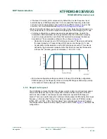
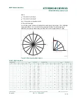
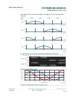
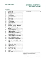
In micro-step mode, a full-step is divided into smaller steps (micro-steps). The LVHBridge
component offers 2, 4, 8, 16 and 32 micro-steps per full-step. The micro-step size is
defined by the property "Micro-steps per Step" and can be changed later in C code.
Figure 23. Micro-stepping phase diagram
Table 12. Micro-step phase
Micro-step size
[1]
I [% of I
MAX
]
Micro-step size
I [% of I
MAX
]
1/2
1/4
1/8
1/16
1/32
Angle
A
B
1/2
1/4
1/8
1/16
1/32
Angle
A
B
0
0
0
0
0
0.0
0
100
4
8
16
32
64
180
0
−100
1
2.8
4.91
99.88
65
182.8
−4.91
−99.88
1
2
5.6
9.8
99.52
33
66
185.6
−9.8
−99.52
3
8.4
14.67
98.92
67
188.4
−14.67
−98.92
1
2
4
11.3
19.51
98.08
17
34
68
191.3
−19.51
−98.08
5
14.1
24.3
97
69
194.1
−24.3
−97
3
6
16.9
29.03
95.69
35
70
196.9
−29.03
−95.69
7
19.7
33.69
94.15
71
199.7
−33.69
−94.15
1
2
4
8
22.5
38.27
92.39
9
18
36
72
202.5
−38.27
−92.39
9
25.3
42.76
90.4
73
205.3
−42.76
−90.4
5
10
28.1
47.14
88.19
37
74
208.1
−47.14
−88.19
11
30.9
51.41
85.77
75
210.9
−51.41
−85.77
3
6
12
33.8
55.56
83.15
19
38
76
213.8
−55.56
−83.15
13
36.6
59.57
80.32
77
216.6
−59.57
−80.32
7
14
39.4
63.44
77.3
39
78
219.4
−63.44
−77.3
15
42.2
67.16
74.1
79
222.2
−67.16
−74.1
1
2
4
8
16
45
70.71
70.71
5
10
20
40
80
225
−70.71
−70.71
17
47.8
74.1
67.16
81
227.8
−74.1
−67.16