


NXP Semiconductors
KTFRDM34933EVBUG
FRDM-34933EVB evaluation board
KTFRDM34933EVBUG
All information provided in this document is subject to legal disclaimers.
© NXP B.V. 2017. All rights reserved.
User guide
Rev. 1.0 — 15 March 2017
24 / 39
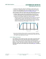
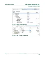
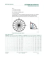
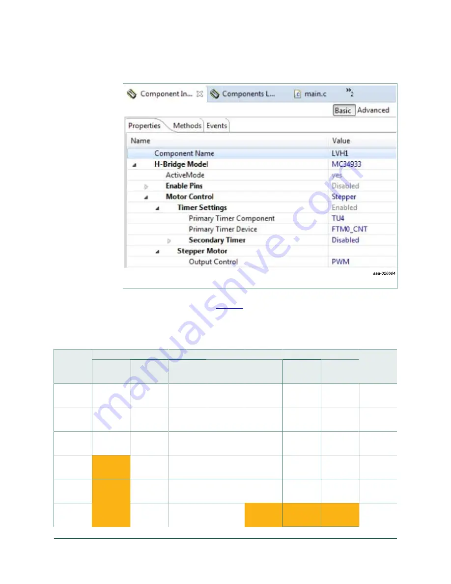
Figure 11. Stepper mode configuration that affects minimum full-stepping speed
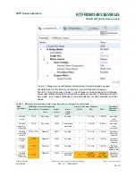
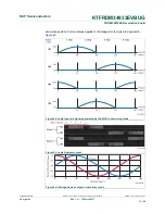
Possible values for the timer input frequency (counter frequency property in
TimerUnit_LDD) are shown in
Table 11
. Input frequency values depend on LVHBridge
component settings. Note that two frequency values are needed in "full-step and micro-
step mode". In one case LVHBridge component switches in runtime between these two
values.
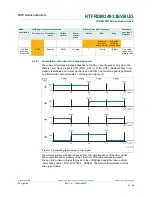
Table 11. Minimum and maximum timer input frequency per stepper control mode
LVHBridge component properties
Primary timer input frequency
Mode
description
Timer device Secondary
timer
Output
control
Motor
control
mode
Values
Min.
Max.
Secondary
timer input
frequency
Full-step
mode
TPM
Don't care
PWM
Full-step
1
131 kHz
1.0 MHz
Any value
(user
selection)
Full-step
and micro-
step mode
TPM
Don't care
PWM
Full-step and
micro-step
1
1.2 MHz
10 MHz
Any value
(user
selection)
Full-step
mode (SW
control)
FTM or TPM
Disabled
GPIO
Full-step
1
131 kHz
1.0 MHz
Secondary
timer is not
enabled
Full-step
mode
FTM
Disabled
PWM
Full-step
1
131 kHz
1.0 MHz
Secondary
timer is not
enabled
Full-step
mode
FTM
Enabled
PWM
Full-step
1
131 kHz
1.0 MHz
The same
values as for
primary timer
Full-step
and micro-
step mode
FTM
Disabled
PWM
Full-step and
micro-step
2
1st value
for full-step:
131 kHz
1st value
for Full-
step: 1 MHz
Secondary
timer is not
enabled